
The HD44780 Standard: Why the 16x2 LCD Endures in 2026
Despite the proliferation of cheap OLEDs and TFT touchscreens, the classic LCD 16x2 Arduino integration remains a cornerstone of embedded prototyping. Built around the ubiquitous Hitachi HD44780 controller (or modern equivalents like the SPLC780D), the 1602A module offers unmatched readability in high-ambient-light environments, draws minimal current (typically 20mA without backlight), and costs between $2.50 and $5.00 for bare parallel modules. However, the wiring methodology you choose—direct 4-bit parallel vs. I2C backpack—drastically alters your GPIO footprint, code complexity, and refresh overhead.
This guide provides a definitive, fluff-free breakdown of wiring topologies, logic-level considerations for modern 3.3V microcontrollers, and production-ready C++ implementation strategies.
Hardware Topology: Parallel vs. I2C Backpack
Before soldering, you must decide on the interface. Direct parallel wiring offers raw speed but consumes precious GPIO pins. The I2C backpack (utilizing a PCF8574 or PCF8574A I/O expander) reduces the wiring to four pins but introduces bus overhead.
| Feature | 4-Bit Parallel (Direct) | I2C Backpack (PCF8574) |
|---|---|---|
| GPIO Pins Required | 6 (RS, E, D4, D5, D6, D7) | 2 (SDA, SCL) |
| Typical Module Cost (2026) | $2.50 - $4.00 | $5.50 - $8.00 (Pre-soldered) |
| Wiring Complexity | High (requires breadboard/PCB routing) | Low (standard 4-pin JST or Dupont) |
| Arduino Library | LiquidCrystal (Built-in) |
LiquidCrystal_I2C (Third-party) |
| Bus Contention Risk | None | Moderate (shared I2C bus) |
Step-by-Step Wiring Guide
Method A: 4-Bit Parallel Wiring
For direct wiring, we use the 4-bit mode to save pins. You will need to connect the following LCD pins to your Arduino Uno (ATmega328P):
- Pin 1 (VSS): GND
- Pin 2 (VDD): 5V
- Pin 3 (V0): Contrast control. Connect to the wiper of a 10kΩ potentiometer (ends to 5V and GND). Pro-tip: A fixed 1kΩ resistor to GND often yields perfect contrast without the pot.
- Pin 4 (RS): Arduino D12
- Pin 5 (RW): GND (Hardwired to Write mode)
- Pin 6 (E): Arduino D11
- Pins 7-10: Not connected
- Pin 11 (D4): Arduino D5
- Pin 12 (D5): Arduino D4
- Pin 13 (D6): Arduino D3
- Pin 14 (D7): Arduino D2
- Pin 15 (A): 5V (Backlight Anode - verify if your module has an onboard resistor; if not, add a 100Ω resistor).
- Pin 16 (K): GND (Backlight Cathode)
Method B: I2C Backpack Wiring (Recommended)
The I2C backpack translates serial I2C data into parallel signals for the HD44780. This is the standard for 90% of modern projects.
- GND: Common Ground
- VCC: 5V (Crucial: Standard 1602A modules require 5V for the LCD logic and backlight).
- SDA: Arduino Uno A4 / Mega D20 / ESP32 GPIO21
- SCL: Arduino Uno A5 / Mega D21 / ESP32 GPIO22
⚠️ 2026 Logic-Level Warning: If you are using a 3.3V microcontroller (ESP32, RP2040, Arduino Nano 33 IoT), do not connect 5V I2C lines directly to 3.3V GPIO pins. While some ESP32 pins are 5V tolerant, it is best practice to use a bidirectional logic level shifter (like the BSS138-based SparkFun BOB-12009, ~$3.50) or purchase a specific 3.3V LCD module with an integrated 3.3V regulator and logic matching.
Arduino Code Implementation
Phase 1: Finding the I2C Address (The #1 Failure Point)
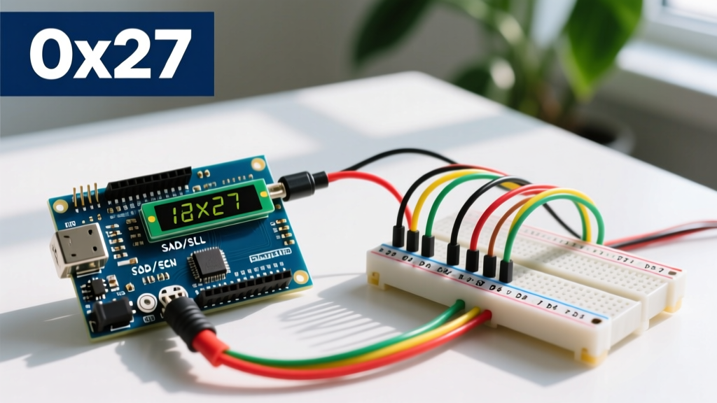
Before writing display code, you must identify the I2C address. Backpacks typically use either the PCF8574 (address 0x27) or PCF8574A (address 0x3F). Guessing this will result in a blank screen. Upload the Arduino I2C Scanner sketch from the official Arduino Playground. Open the Serial Monitor at 115200 baud; the scanner will output the exact hex address of your display.
Phase 2: I2C "Hello World" Sketch
Install the LiquidCrystal I2C library by Frank de Brabander via the Arduino Library Manager. Below is an optimized initialization sequence.
#include <Wire.h>
#include <LiquidCrystal_I2C.h>

// Initialize with address 0x27, 16 columns, 2 rows
LiquidCrystal_I2C lcd(0x27, 16, 2);

void setup() {
  lcd.init();          // Initialize the LCD
  lcd.backlight();     // Turn on the backlight

  // Print static text
  lcd.setCursor(0, 0);
  lcd.print("ElectricalFlux");

  lcd.setCursor(0, 1);
  lcd.print("Booting 2026...");
  delay(2000);
  lcd.clear();
}

void loop() {
  // Display dynamic sensor data
  float tempC = analogRead(A0) * (5.0 / 1023.0) * 100.0; // LM35 example
  lcd.setCursor(0, 0);
  lcd.print("Temp: ");
  lcd.print(tempC, 1);
  lcd.print((char)223); // Degree symbol
  lcd.print("C   ");
  delay(500);
}
Advanced Feature: Custom CGRAM Characters
The HD44780 controller includes 64 bytes of Character Generator RAM (CGRAM), allowing you to define up to 8 custom 5x8 pixel characters. This is essential for creating battery indicators, custom arrows, or proprietary brand logos without relying on external graphical displays.
// Define a custom 'Thermometer' icon
byte thermometer[8] = {
  B00100,
  B01010,
  B01010,
  B01010,
  B01010,
  B10001,
  B11111,
  B01110
};

void setup() {
  lcd.init();
  lcd.createChar(0, thermometer); // Store in CGRAM slot 0
  lcd.setCursor(0,0);
  lcd.write((byte)0); // Print custom character
}
For a visual grid to design your custom byte arrays, refer to the official Arduino LiquidCrystal Reference, which documents the CGRAM mapping and memory limitations.
Troubleshooting & Edge Cases
When your LCD 16x2 Arduino setup fails, it is almost always due to one of the following hardware edge cases:
- White Boxes on Top Row: The LCD is receiving power, but the microcontroller is not communicating. Check your I2C address, verify SDA/SCL are not swapped, and ensure you have 4.7kΩ pull-up resistors on the I2C lines (most backpacks include these, but some cheap clones omit them).
- Completely Blank Screen: The contrast potentiometer (V0) is misadjusted. Take a small Phillips screwdriver and turn the blue potentiometer on the back of the module until the pixels become visible. If using I2C, also check the backlight jumper on the backpack; if removed, the backlight will not illuminate.
- Garbled Text / Random Characters: This indicates a timing violation or power sag. The HD44780 requires strict microsecond timing for the Enable (E) pin. If you are using long jumper wires (>15cm) in a noisy environment, parasitic capacitance will degrade the signal edges. Keep wires short or switch to I2C.
- I2C Bus Lockup: If the ESP32 or Arduino freezes when calling
lcd.print(), the I2C bus has locked up due to a missing ACK. Implement a hardware watchdog timer (WDT) or use the PCF8574 datasheet guidelines to ensure proper bus capacitance limits (max 400pF) are respected.
Summary
Integrating an LCD 16x2 with an Arduino remains a highly efficient way to display diagnostic data, sensor readings, and system states. By leveraging an I2C backpack, you preserve critical GPIO pins for sensors and actuators while maintaining clean, readable code. Always verify your I2C address prior to deployment, respect 5V vs 3.3V logic boundaries, and utilize CGRAM for custom UI elements to elevate your project's professional finish.