
The Evolution of Arduino Pressure Sensing in 2026
Integrating a pressure sensor for Arduino projects has evolved significantly over the last decade. While early hobbyists relied on fragile, raw analog piezoresistive elements, the 2026 landscape is dominated by highly integrated MEMS (Micro-Electromechanical Systems) digital sensors. These modern ICs feature onboard ADCs, temperature compensation, and programmable IIR (Infinite Impulse Response) filters. However, having superior hardware is only half the battle; writing robust driver code and selecting the correct library architecture is what separates a failing prototype from a deployment-ready instrument.
This guide bypasses generic tutorials to provide a deep-dive into the library ecosystems, I2C/SPI driver configurations, and low-level register nuances for the most popular pressure sensors used in the Arduino ecosystem today.
Digital vs. Analog: Choosing the Right Driver Approach
Before writing a single line of C++, you must define your sensor's communication protocol. Digital sensors (I2C/SPI) offload signal conditioning to the sensor's internal ASIC, requiring complex initialization libraries. Analog sensors output a raw voltage, requiring you to write custom ADC scaling math instead of importing a library.
| Sensor Model | Interface | Recommended Library | Resolution | Avg. Price (2026) |
|---|---|---|---|---|
| Bosch BMP280 | I2C / SPI | Adafruit_BMP280 | 0.16 Pa | $1.50 - $2.50 |
| Bosch BME280 | I2C / SPI | Adafruit_BME280 | 0.16 Pa | $3.50 - $5.00 |
| Honeywell ABP2 | I2C / SPI | Wire.h (Custom) | 14-bit to 16-bit | $8.00 - $15.00 |
| NXP MPX5010DP | Analog (Voltage) | N/A (Custom Math) | ADC Dependent | $4.00 - $6.00 |
Deep Dive: Bosch BMP280 & BME280 I2C Driver Setup
The Bosch BMP280 (barometric pressure/temperature) and BME280 (adds humidity) remain the gold standard for hobbyist and light-industrial Arduino projects. According to the official Bosch Sensortec documentation, these sensors require precise configuration of their oversampling registers to achieve their datasheet-claimed noise floors.
Hardware Wiring & Pull-Up Resistor Rules
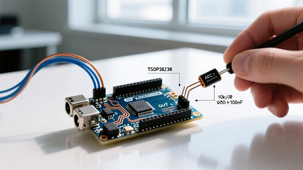
A critical failure mode when using these sensors with 5V Arduino boards (like the Uno R3 or Mega2560) is logic-level mismatch. The BMP280/BME280 operate strictly at 3.3V. Feeding 5V into the I2C SDA/SCL lines will degrade the internal ESD protection diodes over time, leading to intermittent bus lockups.
- Level Shifting: Always use a bidirectional logic level shifter (e.g., a BSS138 MOSFET-based module, approx. $1.20) between the 5V Arduino and the 3.3V sensor.
- Pull-Up Resistors: The breakout boards usually include 10kΩ pull-ups. For I2C buses running at 400kHz (Fast Mode), 10kΩ is often too weak due to bus capacitance. Add parallel 4.7kΩ resistors to bring the equivalent pull-down resistance to ~3.2kΩ, ensuring crisp signal edges.
- I2C Addressing: Tie the SDO pin to GND for address
0x76, or to VCC (3.3V) for0x77. Leaving SDO floating will cause unpredictable address toggling on boot.
Adafruit Library Configuration & IIR Filtering
The Adafruit BME280 Library abstracts the register maps, but default settings are optimized for low power, not low noise. To configure the driver for high-precision altimetry or weather monitoring, you must override the default sampling modes.
#include <Wire.h>
#include <Adafruit_BME280.h>

Adafruit_BME280 bme;

void setup() {
  Serial.begin(115200);
  // Initialize with specific I2C address
  if (!bme.begin(0x76)) {
    Serial.println("Could not find a valid BME280 sensor, check wiring!");
    while (1);
  }

  // Configure for weather monitoring (low power, low noise)
  bme.setSampling(Adafruit_BME280::MODE_FORCED,
                  Adafruit_BME280::SAMPLING_X1,  // Temperature
                  Adafruit_BME280::SAMPLING_X1,  // Pressure
                  Adafruit_BME280::SAMPLING_X1,  // Humidity
                  Adafruit_BME280::FILTER_X16,   // IIR Filter Coefficient
                  Adafruit_BME280::STANDBY_MS_1000);
}
Expert Insight: Mitigating Self-Heating Errors
If you run the BMP280/BME280 inMODE_NORMALwith continuous maximum oversampling, the sensor's internal ASIC will generate up to +1.5°C of self-heating. This skews both temperature and pressure readings (due to thermal expansion inside the MEMS cavity). For precision applications, useMODE_FORCEDand trigger readings manually with a 2-second delay between samples to allow the silicon to reach thermal equilibrium with the ambient air.
High-Precision Industrial: Honeywell ABP2 Series
For applications requiring medical-grade or industrial pneumatic monitoring (e.g., CPAP machines, HVAC differential pressure), the Honeywell ABP2 series is the 2026 standard. Unlike the Bosch environmental sensors, the ABP2 is not supported by mainstream hobbyist libraries. You must write a custom driver using the native Arduino Wire.h library.
Writing the Custom I2C Driver
The ABP2 outputs a 14-bit or 16-bit digital word representing the pressure. The driver must handle the sensor's specific diagnostic flags embedded in the two most significant bits (MSBs) of the first byte.
- Bit 15-14 (Status):
00= Normal,01= Command Mode,10= Stale Data,11= Diagnostic Fault. - Transfer Function: Before coding, check your specific sensor's datasheet suffix. Transfer Function A (10% to 90% of VDD) and Transfer Function B (5% to 95% of VDD) require different scaling math in your C++ driver.
When coding the Wire.requestFrom() function for the ABP2, always request exactly 4 bytes. The first two bytes contain the pressure data and status flags, while the latter two contain the onboard temperature sensor data, which is vital for compensating external thermal drift in unregulated environments.
Analog Sensors (MPX5010): Bypassing Libraries for Raw ADC
Not every project requires an I2C bus. The NXP MPX5010DP is a differential analog pressure sensor widely used for water level sensing and basic pneumatics. Because it outputs a ratiometric analog voltage, no external library is required, but your driver code must implement the precise transfer function.
ADC Scaling and Ratiometric Math
The MPX5010 operates on a 5V supply. Its output voltage ($V_{out}$) follows this factory-calibrated equation:
V_out = V_S * (0.09 * P + 0.04)
Where $V_S$ is the supply voltage (5.0V) and $P$ is the pressure in kPa. If you are using a standard 5V Arduino Uno with a 10-bit ADC (1024 steps), each ADC step represents 4.88mV. Your driver code should look like this:
const int analogPin = A0;
const float V_supply = 5.0;

void loop() {
  int rawADC = analogRead(analogPin);
  float voltage = (rawADC / 1024.0) * V_supply;

  // Invert the transfer function to solve for Pressure (kPa)
  float pressure_kPa = (voltage / V_supply - 0.04) / 0.09;

  Serial.print("Pressure: ");
  Serial.print(pressure_kPa);
  Serial.println(" kPa");
  delay(500);
}
Edge Case Warning: Analog sensors are highly susceptible to EMI (Electromagnetic Interference) from nearby stepper motors or switching power supplies. Always implement a software moving-average filter (e.g., averaging 20 consecutive samples) and place a 100nF ceramic capacitor directly across the sensor's VCC and GND pins at the physical connector.
Troubleshooting I2C Bus Lockups & Address Collisions
When integrating multiple sensors on a single Arduino I2C bus, driver initialization failures are common. Here is a diagnostic framework for resolving them:
- Bus Capacitance Overload: The I2C specification limits total bus capacitance to 400pF. Long wires (>30cm) or chaining more than 4 sensors will cause signal degradation. Fix: Reduce I2C clock speed to 100kHz using
Wire.setClock(100000);or use an I2C bus extender IC like the PCA9600. - Memory Leaks in Libraries: Some poorly maintained third-party pressure libraries allocate memory dynamically inside the
loop()function usingStringobjects ormalloc. Over 48 hours, this will crash an ATmega328P. Fix: Audit the library's source code. Ensure all variables are declared globally or statically, and use character arrays instead of theStringclass for data formatting. - Stale Data Reads: If your Arduino polls the sensor faster than its internal conversion time, you will read the exact same pressure value repeatedly. Fix: Check the sensor's maximum Output Data Rate (ODR). For the BMP280 at maximum oversampling, the conversion time is ~250ms. Polling at 10Hz will yield stale data. Implement a non-blocking
millis()timer in your driver to respect the ODR.
Summary
Selecting the right pressure sensor for Arduino hardware is only the first step. Whether you are configuring the IIR filters on a Bosch BME280, writing custom bitwise operations for a Honeywell ABP2, or scaling raw ADC voltages from an MPX5010, understanding the underlying driver mechanics is essential. By respecting logic-level thresholds, managing bus capacitance, and mitigating thermal self-heating, your pressure sensing projects will achieve the reliability required for real-world deployment.