
The Enduring Relevance of the Arduino 16x2 LCD Display in 2026
Despite the proliferation of high-resolution OLEDs and TFT touchscreens, the Arduino 16x2 LCD display remains a staple in industrial prototyping, automotive dashboards, and ruggedized DIY electronics. Based on the ubiquitous Hitachi HD44780 controller (or modern equivalents like the SPLC780D), these modules offer unmatched readability in direct sunlight, extreme temperature tolerance, and 5V logic compatibility without the need for fragile ribbon cables.
At ElectricalFlux, we frequently field questions about integrating these displays into modern 3.3V ecosystems like the ESP32-S3 or Raspberry Pi Pico. This comprehensive wiring and code guide bridges the gap between legacy 5V parallel interfaces and modern I2C bus architectures, providing exact pinouts, timing constraints, and failure-mode troubleshooting.
Hardware Economics: Parallel vs. I2C Backpack Modules
When sourcing an Arduino 16x2 LCD display, you will encounter two primary variants. The bare 16-pin module requires extensive GPIO routing, while the I2C-equipped module utilizes a PCF8574 or MCP23008 expander chip mounted on the rear PCB. As of 2026, supply chain stabilization has driven the cost of bare modules to roughly $2.10–$3.50, while I2C variants sit between $3.80–$5.50 depending on the backlight color and bezel quality.
| Feature | 16-Pin Parallel (Bare) | I2C Backpack (PCF8574) |
|---|---|---|
| MCU GPIO Pins Required | 6 (4-bit mode) or 10 (8-bit) | 2 (SDA, SCL) |
| Wiring Complexity | High (requires breadboard/PCB routing) | Low (4-wire bus) |
| Bus Capacitance Limit | N/A (Direct drive) | 400pF (Standard I2C spec) |
| Logic Level Tolerance | 5V Strict (Requires level shifting for 3.3V) | 5V Strict (Backlight requires 4.2V+) |
Wiring Guide 1: The I2C Standard (Recommended)
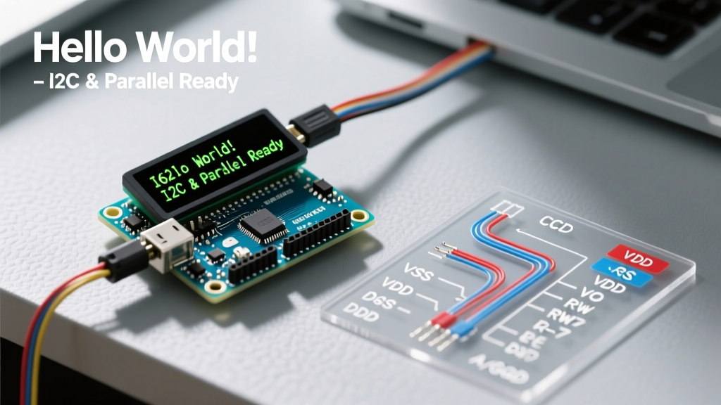
For 90% of modern projects, the I2C backpack is the superior choice. The most common expander chip is the NXP PCF8574, which translates I2C serial data into parallel signals for the HD44780. According to SparkFun's I2C Tutorial, the I2C bus requires pull-up resistors, which are typically pre-soldered onto the LCD backpack (usually 4.7kΩ to 10kΩ).
I2C Pinout & Connections
- GND: Connect to MCU Ground.
- VCC: Connect to 5V. Critical Edge Case: The backlight LED array has a forward voltage of ~4.2V. Powering VCC with 3.3V will result in a blank screen because the backlight will not illuminate, even if the logic chip powers up.
- SDA: Connect to MCU I2C Data pin (Arduino Uno: A4, ESP32: GPIO 21, Pico: GPIO 0).
- SCL: Connect to MCU I2C Clock pin (Arduino Uno: A5, ESP32: GPIO 22, Pico: GPIO 1).
Expert Tip: If you are interfacing a 5V I2C LCD with a 3.3V microcontroller (like the ESP32), the PCF8574's I2C pull-up resistors will pull the SDA/SCL lines to 5V, potentially damaging your MCU's GPIO pins over time. Use a bidirectional logic level shifter (e.g., NXP PCA9306) or physically desolder the backpack pull-ups and rely on the MCU's internal 3.3V pull-ups.
Wiring Guide 2: 4-Bit Parallel (Legacy Fallback)
If you are out of I2C addresses or working with an ATtiny85 where I2C overhead is too costly, the 4-bit parallel mode is your fallback. This requires referencing the official Arduino LiquidCrystal Library documentation to map the pins correctly.
- RS (Register Select): Digital Pin 12
- RW (Read/Write): Connect directly to GND. (Tying this low forces the LCD into Write-only mode, saving a GPIO pin and preventing bus contention).
- EN (Enable): Digital Pin 11
- D4 to D7: Digital Pins 5, 4, 3, 2 respectively.
- V0 (Contrast): Connect to the wiper of a 10kΩ potentiometer. The other legs go to 5V and GND.
Code Implementation & Library Configuration
For I2C modules, the community-standard LiquidCrystal_I2C library by Frank de Brabander is the most robust option. Below is the optimized initialization sequence for 2026 toolchains, including Fast I2C clock adjustments to prevent screen tearing during rapid data logging.
#include <Wire.h>
#include <LiquidCrystal_I2C.h>

// Initialize with I2C address 0x27, 16 columns, 2 rows
LiquidCrystal_I2C lcd(0x27, 16, 2);

void setup() {
  Wire.begin();
  Wire.setClock(400000); // Enable 400kHz Fast I2C to reduce bus blocking
  lcd.init();
  lcd.backlight();

  // Custom character generation (CGRAM)
  byte tempIcon[8] = {0x04,0x0E,0x0E,0x0E,0x1F,0x1F,0x1F,0x0E};
  lcd.createChar(0, tempIcon);

  lcd.setCursor(0, 0);
  lcd.write((uint8_t)0); // Print custom temp icon
  lcd.print(" Flux: 72.4C");
}
Address Scanning & The 0x27 vs 0x3F Dilemma
A frequent point of failure is assuming the I2C address. Modules using the PCF8574T chip default to 0x27 (with A0, A1, A2 pads unbridged). Modules using the PCF8574AT chip default to 0x3F. If your code compiles but the screen remains blank, run a standard I2C Scanner sketch to poll the bus and verify the exact hexadecimal address before hardcoding it.
Mastering CGRAM for Custom Icons
The HD44780 controller features 64 bytes of Character Generator RAM (CGRAM), allowing you to define up to eight custom 5x8 pixel characters. This is essential for displaying battery indicators, temperature glyphs, or proprietary brand logos without relying on external graphic libraries. Note that CGRAM is volatile; custom characters must be redefined if the LCD loses power or undergoes a hard reset.
Backlight PWM and Transistor Switching
The I2C backpack includes a small SMD NPN transistor (usually an MMBT3904) to switch the backlight LED array. The jumper on the backpack connects this transistor to VCC. If you remove the jumper, you can wire the exposed LED pin to a PWM-capable GPIO on your Arduino to dynamically dim the backlight based on ambient light sensor readings, saving up to 120mA of current draw in battery-operated nodes.
Advanced Troubleshooting & Edge Cases
1. Contrast Drift and Temperature Coefficients
The standard 10kΩ trimpot on the back of I2C backpacks (or required for parallel setups) is highly susceptible to thermal drift. In outdoor enclosures experiencing -10°C to 40°C swings, the liquid crystal fluid viscosity changes, causing the text to fade or turn into solid black blocks. Solution: Replace the mechanical trimpot with a fixed resistor network calculated for your specific operating temperature, or use a digital potentiometer (like the MCP4131) controlled via SPI to auto-calibrate contrast based on an onboard thermistor.
2. Ghosting and Power Supply Decoupling
When the LCD backlight toggles on and off, or when updating the screen rapidly, you may notice "ghosting" (faint remnants of previous characters) or MCU brownouts. The HD44780 controller and the backlight LED array draw transient current spikes up to 150mA. Solution: Solder a 100nF (0.1µF) ceramic decoupling capacitor directly across the VCC and GND pins on the rear of the LCD PCB, as close to the controller IC as possible. This local energy reservoir prevents voltage sag on the main MCU rail.
3. The "Black Boxes on Row 1" Initialization Failure
If your display powers on showing a row of solid black rectangles on the top line, and nothing on the bottom line, the HD44780 has failed to execute its internal power-on reset (POR) sequence. This occurs when the 5V rail rises too slowly (e.g., when powered via a high-capacitance USB hub). The LCD's internal POR requires VCC to reach 4.5V within 15ms. Solution: Add a delay(1000); at the very beginning of your setup() loop before calling lcd.init(), allowing the power supply to stabilize before sending software initialization commands.
Summary
Mastering the Arduino 16x2 LCD display requires moving beyond basic copy-paste tutorials. By understanding the underlying HD44780 architecture, respecting I2C logic-level boundaries, and implementing proper hardware decoupling, you can build rugged, reliable interfaces that outlast modern fragile OLED alternatives in harsh environments.