
Understanding the Anatomy of Hobby Servos
Unlike standard DC motors that spin continuously, servo motors for Arduino projects are closed-loop systems designed for precise angular positioning. Inside the plastic or metal casing, you will find a small DC motor, a reduction gearbox, a potentiometer (which acts as the position feedback sensor), and a control circuit. The control circuit reads the potentiometer's voltage to determine the shaft's current angle and compares it to the incoming PWM (Pulse Width Modulation) signal from your microcontroller. If there is a discrepancy, the H-bridge inside the servo drives the motor until the target angle is reached.
Standard hobby servos operate on a 50Hz PWM signal, meaning a new pulse is sent every 20 milliseconds (ms). The width of the high pulse dictates the angle: typically, a 500-microsecond (µs) pulse commands 0 degrees, a 1500µs pulse commands 90 degrees (center), and a 2400µs pulse commands 180 degrees. Understanding this timing is critical when debugging erratic behavior or writing custom driver code without relying on bloated libraries.
Choosing the Right Servo Motors for Arduino
Selecting the correct servo depends entirely on your mechanical load, power budget, and required precision. In 2026, the market is dominated by three primary tiers of hobby servos. Below is a comparison matrix to help you choose the right actuator for your build.
| Model | Type | Stall Torque (at 6V) | Weight | Est. Price (2026) | Best Use Case |
|---|---|---|---|---|---|
| TowerPro SG90 | Analog / Nylon | 1.8 kg-cm | 9g | $2.50 | Pan/tilt camera mounts, lightweight robotic arms, educational kits. |
| TowerPro MG996R | Analog / Metal | 13.0 kg-cm | 55g | $7.00 | RC car steering, heavy-duty robotic joints, automated latches. |
| DS3218 (Generic) | Digital / Metal | 20.0 kg-cm | 60g | $15.00 | Hexapod walking robots, high-precision gimbals requiring 333Hz update rates. |
Note: Digital servos like the DS3218 process the PWM signal via a microcontroller rather than an analog comparator, allowing them to update the motor drive at much higher frequencies (up to 333Hz vs the standard 50Hz), resulting in tighter holding torque and faster transient response.
Wiring Diagrams and Power Supply Rules
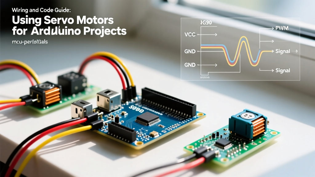
The most common point of failure for beginners integrating servo motors for Arduino is inadequate power delivery. The Arduino's onboard 5V regulator is typically rated for 500mA to 800mA maximum. An SG90 draws roughly 200mA under load, which is manageable. However, an MG996R can spike to 2.5 Amps during a stall condition. Connecting an MG996R directly to the Arduino 5V pin will cause a brownout, resetting the microcontroller and potentially damaging the USB port or voltage regulator.
The Golden Rule: External Power for High-Torque Servos
Critical Warning: Always use an external BEC (Battery Eliminator Circuit) or a dedicated 5V/6V power supply rated for at least 3A per high-torque servo. Furthermore, the external power supply's ground (GND) must be tied directly to the Arduino's GND to establish a common reference voltage for the PWM signal.
Step-by-Step Wiring for an MG996R
- Power the Servo: Connect the red wire (VCC) of the MG996R to the positive terminal of a 5V 3A UBEC. Connect the black/brown wire (GND) to the UBEC negative terminal.
- Establish Common Ground: Run a jumper wire from the UBEC negative terminal to any GND pin on your Arduino.
- Route the Signal: Connect the orange/yellow wire (Signal) to a PWM-capable digital pin on the Arduino (e.g., Pin 9).
- Add Bulk Capacitance: Solder a 470µF electrolytic capacitor across the VCC and GND wires as close to the servo connector as possible. This absorbs the massive inductive current spikes during motor startup, preventing voltage sags.
Arduino Code Implementation
While you can generate 50Hz PWM signals manually using hardware timers, the standard Arduino Servo Library abstracts this beautifully by handling the timer interrupts required to maintain the 20ms pulse train in the background.
Basic Sweep with the Servo Library
The following code demonstrates basic attachment, movement, and the crucial detach() function.
#include <Servo.h>

Servo myServo;

void setup() {
  // Attach servo to pin 9, specifying custom min/max pulse widths (in µs)
  myServo.attach(9, 500, 2400);
  myServo.write(90); // Move to center
  delay(1000);
}

void loop() {
  myServo.write(0);
  delay(2000);
  myServo.write(180);
  delay(2000);

  // Detaching removes the PWM signal, stopping internal jitter
  // and saving power when the servo is not actively moving.
  myServo.detach();
  delay(5000);
  myServo.attach(9, 500, 2400);
}
Non-Blocking Servo Control (Production Ready)
Using delay() is unacceptable in production firmware, as it blocks the microcontroller from reading sensors or handling serial communication. Below is a professional, non-blocking implementation using millis() to smoothly interpolate the servo angle without halting the main loop.
#include <Servo.h>

Servo myServo;
unsigned long previousMillis = 0;
const long interval = 20; // 20ms update rate (matches 50Hz PWM standard)
int targetAngle = 90;
int currentAngle = 0;

void setup() {
  myServo.attach(9, 500, 2400);
  myServo.write(currentAngle);
}

void loop() {
  // Non-blocking timing logic
  unsigned long currentMillis = millis();
  if (currentMillis - previousMillis >= interval) {
    previousMillis = currentMillis;

    // Smooth interpolation
    if (currentAngle < targetAngle) {
      currentAngle++;
      myServo.write(currentAngle);
    } else if (currentAngle > targetAngle) {
      currentAngle--;
      myServo.write(currentAngle);
    }
  }

  // Add your sensor reading or serial parsing code here
}
Troubleshooting Jitter, Overheating, and Stripping
Even with perfect code, physical and electrical anomalies can plague servo motors for Arduino. Here is how to diagnose and fix the most common edge cases:
- Idle Jitter (The 'Twitch' Effect): If your servo vibrates slightly while holding a position, it is usually caused by a noisy power supply or a floating signal pin. Fix: Ensure your 470µF capacitor is installed. Additionally, wire a 10kΩ pulldown resistor between the Arduino PWM pin and GND to keep the signal line low during microcontroller boot-up sequences.
- Overheating and Current Draw: If a servo becomes too hot to touch, it is likely being forced against a mechanical hard stop while the microcontroller continues to command a different angle. The motor is stalled, drawing maximum current continuously. Fix: Implement software limits in your code to prevent commanding angles beyond the physical constraints of your mechanism, or use current-sensing resistors to detect stalls and cut power.
- Gear Stripping: Nylon gears (found in the SG90) will strip instantly if subjected to shock loads or back-driving. Fix: Upgrade to metal-gear servos (MG996R) for any application involving kinetic impacts or high inertia loads. Ensure you are using the correct servo horn and securing it with the provided M3 or M4 retaining screw.
Scaling Up: The PCA9685 I2C Driver
If your project requires more than two or three servos—such as a 6-DOF robotic arm or a quadruped robot—you will quickly run out of hardware timer pins on the Arduino. Furthermore, the standard Servo library can conflict with other libraries that rely on Timer1 (like certain ultrasonic sensor or IR remote libraries).
The industry-standard solution is the PCA9685 16-Channel PWM Driver. This I2C breakout board handles all 50Hz pulse generation on its own dedicated chip, requiring only two wires (SDA and SCL) to communicate with the Arduino. According to the official NXP PCA9685 datasheet, the chip features a 12-bit resolution (4096 steps per pulse), allowing for incredibly fine micro-stepping and ultra-smooth servo actuation that standard 8-bit Arduino PWM simply cannot achieve. For comprehensive wiring and library setup for this chip, refer to the Adafruit 16-Channel PWM/Servo Shield Guide.
By mastering external power delivery, non-blocking code architecture, and I2C expansion, you can reliably integrate servo motors for Arduino into highly complex, production-grade robotics and automation systems.