
The Ultimate Beginner Guide: HD44780 LCD Interfacing
Learning how to connect a LCD to Arduino is a rite of passage for every electronics hobbyist. Despite the rise of OLEDs and TFTs in 2026, the classic 16x2 character LCD based on the Hitachi HD44780 controller remains the most cost-effective and reliable display for sensor readouts, debugging, and DIY control panels. A standard 16x2 module costs roughly $3.50, making it an indispensable tool in any prototyping arsenal.
In this tutorial, we will cover the two primary methods for driving these displays: the modern I2C backpack method (which saves microcontroller pins) and the classic 4-bit parallel method (ideal for understanding digital I/O fundamentals).
Bill of Materials (BOM)
| Component | Specification / Model | Estimated Cost (2026) |
|---|---|---|
| Microcontroller | Arduino Uno R4 Minima | $27.50 |
| Display Module | 16x2 Character LCD (HD44780) | $3.50 |
| I2C Adapter | PCF8574 I2C Backpack Module | $1.20 |
| Potentiometer | Bourns 3386P 10kΩ Trimmer | $0.80 |
| Wiring | 22 AWG Solid Core Jumper Kit | $5.00 |
Method 1: The I2C Backpack Approach (Recommended)
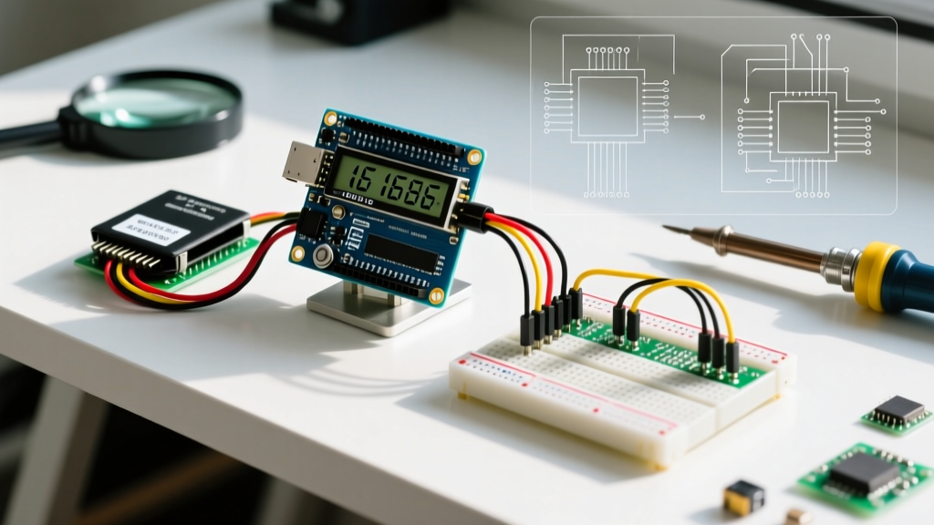
For 95% of modern projects, using an I2C backpack is the superior choice. The backpack utilizes an NXP PCF8574 I/O expander chip to convert serial I2C data into the parallel signals the LCD requires. This reduces your wiring from 12+ cables down to just four.
I2C Pinout and Wiring Table
| Backpack Pin | Arduino Uno R3 / R4 Pin | Function |
|---|---|---|
| GND | GND | Common Ground |
| VCC | 5V | Power (Requires 5V, not 3.3V) |
| SDA | A4 (Uno R3) or SDA (Uno R4) | Serial Data Line |
| SCL | A5 (Uno R3) or SCL (Uno R4) | Serial Clock Line |
Locating Your I2C Address
Before uploading code, you must find the I2C address of your backpack. Most PCF8574 modules default to 0x27 or 0x3F. Upload the standard Arduino I2C Scanner sketch via the Serial Monitor at 9600 baud to confirm. If the address is wrong, your screen will remain blank.
I2C Code Implementation
Install the LiquidCrystal I2C library via the Arduino Library Manager. According to the official Arduino LiquidCrystal documentation, initializing the display requires specifying the address, columns, and rows.
#include <LiquidCrystal_I2C.h>

// Initialize with address 0x27, 16 columns, 2 rows
LiquidCrystal_I2C lcd(0x27, 16, 2);

void setup() {
  lcd.init();
  lcd.backlight();
  lcd.setCursor(0, 0);
  lcd.print("ElectricalFlux");
  lcd.setCursor(0, 1);
  lcd.print("I2C LCD Guide");
}

void loop() {}
Method 2: Classic 4-Bit Parallel Wiring
If you do not have an I2C backpack, or if you are using a microcontroller without hardware I2C (like the ATtiny85), you must wire the LCD in parallel. We use 4-bit mode instead of 8-bit mode because it cuts the data pin requirement in half (from 8 to 4) while only marginally reducing refresh rates—imperceptible for human-readable text.
Parallel Pinout Matrix
| LCD Pin | Symbol | Arduino Connection | Notes |
|---|---|---|---|
| 1 | VSS | GND | Ground |
| 2 | VDD | 5V | Main Power |
| 3 | V0 | Potentiometer Wiper | Contrast Control (0V to 0.5V) |
| 4 | RS | Digital Pin 12 | Register Select |
| 5 | RW | GND | Tie to GND for Write-Only mode |
| 6 | EN | Digital Pin 11 | Enable / Clock |
| 11 | D4 | Digital Pin 5 | Data Bit 4 |
| 12 | D5 | Digital Pin 4 | Data Bit 5 |
| 13 | D6 | Digital Pin 3 | Data Bit 6 |
| 14 | D7 | Digital Pin 2 | Data Bit 7 |
| 15 | A | 5V (via 100Ω resistor) | Backlight Anode |
| 16 | K | GND | Backlight Cathode |
Expert Tip: Never leave the RW (Read/Write) pin floating. If you are only sending data to the screen, tie RW directly to GND. Leaving it unconnected can cause the LCD to enter read mode, resulting in bus contention and potential damage to your Arduino GPIO pins.
Critical Edge Cases & Troubleshooting
Even veterans run into issues when interfacing parallel displays. Here is a diagnostic framework for the most common failure modes encountered in the lab.
1. The White Boxes Initialization Failure
Symptom: The top row displays solid white or black blocks, while the bottom row is blank.
Root Cause: The Arduino is failing to sync the 4-bit nibbles during initialization, or the RW pin is floating.
Fix: Ensure RW is tied to GND. Add a delay(100); immediately after LiquidCrystal object creation in your setup loop to allow the LCD internal power-on reset circuit to stabilize before the MCU sends commands.
2. Backlight On, But No Text (Contrast Voltage Issue)
Symptom: The blue/green backlight is illuminated, but the screen appears completely empty.
Root Cause: The V0 (Pin 3) contrast voltage is outside the optimal 0.1V to 0.4V window.
Fix: Use a multimeter to measure the voltage at the V0 pin while turning your 10kΩ trimmer potentiometer. You are looking for approximately 0.25V. If you do not have a potentiometer, connect V0 to GND via a 1kΩ resistor for a fixed, high-contrast default.
3. Garbage Characters and Flickering
Symptom: Random Japanese characters or flickering blocks appear during sensor polling.
Root Cause: Electromagnetic interference (EMI) on long parallel data lines, or missing internal pull-ups on I2C lines.
Fix: For parallel setups, keep data wires under 15cm. For I2C setups, if your cable run exceeds 30cm, you must add 4.7kΩ pull-up resistors to both SDA and SCL lines to prevent signal degradation.
Logic Level Shifting for 3.3V Microcontrollers
A frequent mistake beginners make in 2026 is connecting a standard 5V HD44780 LCD directly to a 3.3V microcontroller like the ESP32, Raspberry Pi Pico, or Arduino Nano 33 IoT. While the ESP32 GPIO pins are generally 5V tolerant, the LCD will not reliably register 3.3V as a logical HIGH (the HD44780 requires a minimum of 0.7 x VDD, which is 3.5V for a 5V system).
The Solution: Use a bidirectional logic level shifter (like the Texas Instruments SN74AVCH4T245 or a generic BSS138 MOSFET breakout board, costing around $2.50) between your 3.3V MCU and the 5V LCD. This ensures clean signal transitions and prevents long-term degradation of your microcontroller silicon.
Summary: Which Method Should You Choose?
| Feature | I2C Backpack | 4-Bit Parallel |
|---|---|---|
| Wiring Complexity | Low (4 wires) | High (12+ wires) |
| GPIO Pins Used | 2 (SDA, SCL) | 6 (RS, EN, D4-D7) |
| Code Complexity | Low | Medium |
| Refresh Speed | Moderate (I2C overhead) | Fast (Direct GPIO) |
| Best Use Case | Standard sensor dashboards | High-speed data logging, ATtiny projects |
Mastering how to connect a LCD to Arduino unlocks the ability to build standalone, PC-free diagnostic tools. Whether you choose the pin-saving I2C route or the fundamental parallel approach, understanding the underlying hardware constraints—like contrast voltage thresholds and logic level requirements—will separate your projects from amateur builds. Grab your soldering iron, wire up your HD44780, and start building.