
Beyond the Basics: Multi-Peripheral Servo Integration
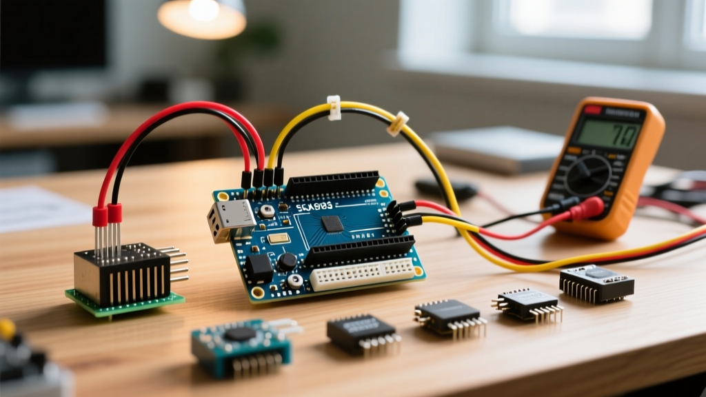
When makers search for servo en arduino, they are typically met with basic tutorials demonstrating a single micro servo sweeping back and forth on Pin 9. While this is a fine starting point for absolute beginners, real-world robotics, automated blinds, and environmental monitoring projects require a robust multi-peripheral setup. Integrating a high-torque servo alongside I2C sensors (like the BME280), SPI TFT displays, and ultrasonic rangefinders introduces complex power distribution and timer conflict challenges. In this 2026 guide, we elevate the standard tutorial into a comprehensive masterclass on multi-peripheral integration, focusing on power isolation, I2C PWM drivers, and non-blocking code architecture.
The Power Bottleneck in Multi-Peripheral Setups
The most common point of failure in multi-servo and sensor networks is power starvation. A standard Arduino Uno R4 Minima or ESP32-S3 development board cannot safely source the current required for high-torque servos while simultaneously powering logic circuits. For example, the popular TowerPro MG996R draws roughly 2.5 amps at stall. If you attempt to power this servo, a 128x64 I2C OLED display, and the microcontroller simultaneously via the Arduino's onboard 5V linear regulator, the regulator will rapidly overheat and trigger thermal shutdown—or worse, fail catastrophically and fry your logic board.
Expert Pro-Tip: Never route high-current servo power through standard solderless breadboard rails. Most breadboard bus strips are rated for roughly 1A to 2A maximum and will introduce severe voltage drops. This resistance causes microcontroller brownouts, erratic I2C sensor readings, and unpredictable servo jitter.
To build a reliable multi-peripheral node, you must use a dedicated step-down buck converter (such as the LM2596 or the more efficient MP2307DN) wired directly to the servo's power terminals, completely bypassing the Arduino's voltage regulator.
2026 Hardware Selection & Component Pricing
Choosing the right actuator is critical when balancing torque requirements against your power budget. Below is a comparison of standard hobby servos frequently used in multi-peripheral builds, reflecting average maker-market pricing and specifications as of 2026.
| Servo Model | Stall Torque | Stall Current | Operating Voltage | 2026 Avg Price |
|---|---|---|---|---|
| TowerPro SG90 | 1.8 kg/cm | 700 mA | 4.8V - 6.0V | $2.50 |
| TowerPro MG90S | 2.2 kg/cm | 1.2 A | 4.8V - 6.0V | $4.00 |
| TowerPro MG996R | 13.0 kg/cm | 2.5 A | 4.8V - 7.2V | $6.50 |
| Savox SC-1258 | 12.5 kg/cm | 3.0 A | 4.8V - 6.0V | $38.00 |
| DS3218 (20kg) | 20.0 kg/cm | 3.5 A | 5.0V - 6.8V | $14.00 |
For multi-sensor arrays where weight and precision matter, the MG90S (metal gear) remains a staple. However, for heavy-duty actuation like robotic arms or automated valve control, the DS3218 offers immense torque, provided your external power supply can handle the 3.5A inrush current.
Timer Conflicts: Servo.h vs. I2C and PWM Peripherals
The native Arduino Servo library is a marvel of simplicity, but it comes with a hidden cost in multi-peripheral environments. On ATmega328P-based boards (like the classic Uno R3), the library hijacks Timer1 to generate the precise 50Hz PWM signals required for servo control. Consequently, hardware PWM is permanently disabled on Pins 9 and 10 while the library is active.
If your multi-peripheral setup includes an L298N motor driver, a piezo buzzer utilizing tone generation, or an IR receiver library that relies on Timer1, your project will experience silent failures or erratic behavior. Furthermore, relying on delay() to sweep a servo blocks the main loop, preventing you from polling I2C sensors like the BME280 at the high frequencies required for accurate environmental tracking.
The PCA9685 Solution: Offloading PWM via I2C
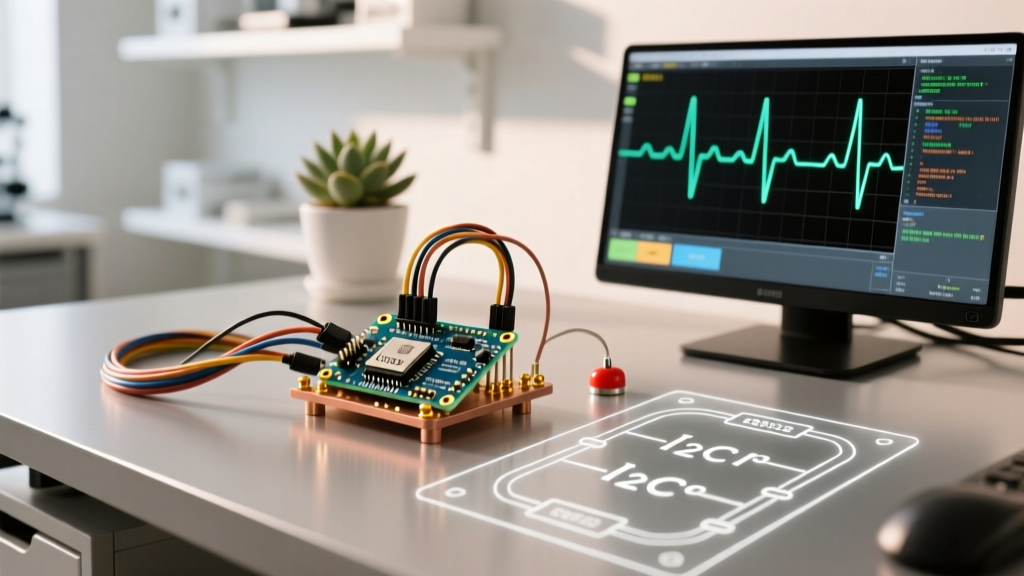
To resolve timer conflicts and scale up to multi-servo arrays, professional makers offload PWM generation to an external I2C driver. The NXP PCA9685 16-channel PWM driver is the industry standard. By utilizing the Adafruit PCA9685 library, your microcontroller only needs to send a few bytes over the I2C bus to set the servo angle. This frees up all hardware timers and digital pins for other peripherals.
The PCA9685 operates at a default I2C address of 0x40 (configurable up to 0x7F via onboard solder jumpers) and features a dedicated V+ terminal block for servo power. This physically isolates the high-current servo rail from your microcontroller's logic voltage, a crucial safety measure in complex builds.
Wiring Architecture & Edge Case Mitigation
Proper wiring is the difference between a prototype that works on a desk and a deployed unit that survives in the field. You must establish a common ground between the Arduino, the PCA9685 logic side, and the high-current servo power supply. Without a shared ground reference, the I2C data signals will float, resulting in corrupted sensor data and servos that snap to full rotation randomly.
Capacitor Placement for Inrush Current
A frequent edge case in complex servo en arduino builds is ground loop interference and voltage sag, which manifests as severe servo jitter or I2C bus lockups. To mitigate this, place a 470µF low-ESR electrolytic capacitor directly across the V+ and GND screw terminals on the PCA9685 board. This capacitor acts as a local energy reservoir, absorbing the massive inrush current when a high-torque servo changes direction under load. According to engineering guidelines from Pololu Robotics, failing to provide adequate local capacitance for high-current servos is the leading cause of microcontroller brownouts in multi-actuator systems.
Non-Blocking Code Architecture
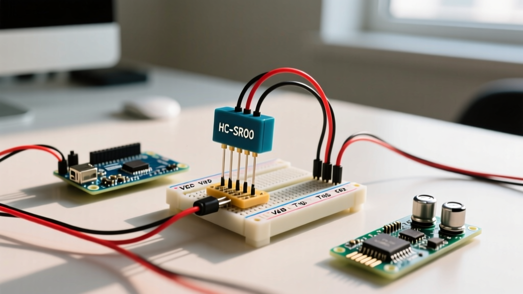
When running a servo alongside an ultrasonic sensor (HC-SR04) and a barometric sensor, you cannot use blocking delays. You must implement a state-machine architecture using millis().
- Sensor Polling State: Trigger the HC-SR04 every 50ms using a non-blocking timer. Calculate distance and store it in a global variable.
- Servo Actuation State: Map the distance variable to a servo angle (e.g., 0 to 180 degrees). Send the I2C command to the PCA9685 to update the PWM pulse width (typically between 150 and 600 microseconds).
- Telemetry State: Read the BME280 over I2C every 2 seconds and format the data for an SPI TFT display or LoRa transmission.
By decoupling the servo command from the physical movement time, your microcontroller remains entirely free to handle interrupt-driven peripherals and high-speed serial communication.
Troubleshooting Multi-Peripheral Failures
1. I2C Bus Dropouts When Servo Moves
Cause: Electromagnetic interference (EMI) from the servo motor brushes coupling into the unshielded I2C SDA/SCL lines.
Fix: Route I2C wires away from servo power cables. If using long I2C runs (over 30cm), reduce the I2C clock speed from 400kHz to 100kHz in your Wire library initialization, and ensure you have 4.7kΩ pull-up resistors on both SDA and SCL lines.
2. Servo Jitter at Rest
Cause: Noisy power supply or poor ground connection.
Fix: Verify the buck converter is outputting a clean DC voltage with minimal ripple. Ensure the signal wire from the PCA9685 to the servo is not running parallel to the high-current power wires.
3. Arduino Randomly Resetting
Cause: Back-EMF from the servo motor feeding back into the logic rail.
Fix: Ensure the servo power is completely isolated from the Arduino 5V pin. The only connection between the high-current rail and the Arduino should be the common ground wire and the PWM signal wire.
Mastering the multi-peripheral servo en arduino setup requires moving beyond simple pin outputs and embracing dedicated power distribution and I2C offloading. By implementing the PCA9685, managing inrush currents with proper capacitance, and writing non-blocking firmware, your electromechanical projects will achieve the reliability required for real-world deployment.