
The Inherent Accuracy Problem with the L298N
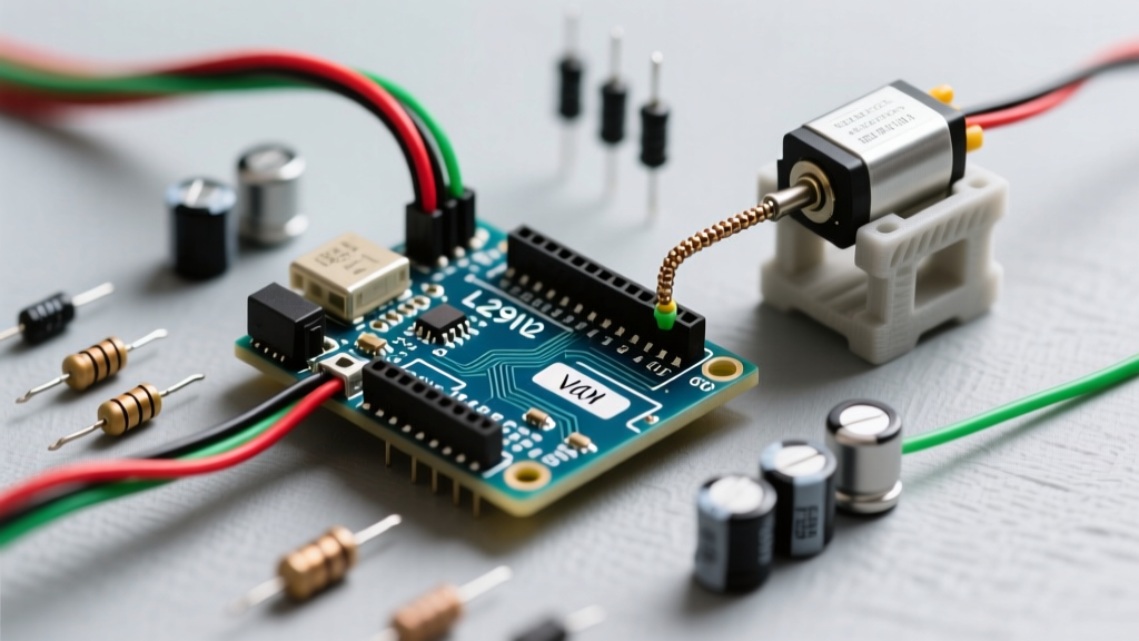
When building DIY robotics or automated platforms, the L298N dual H-bridge module is often the first motor driver hobbyists encounter. Priced between $3 and $5 in 2026, it is ubiquitous and easy to wire. However, achieving true precision with L298N Arduino motor control requires overcoming significant hardware limitations. The L298N relies on older Bipolar Junction Transistor (BJT) Darlington pairs rather than modern MOSFETs. This architecture introduces severe voltage drops and thermal inefficiencies that destroy speed linearity and positional accuracy.
Hardware Reality Check: According to the STMicroelectronics L298N Datasheet, the typical voltage drop across the internal transistors is 1.8V at 1A, and can reach up to 2.5V at 2A. If you supply 7.4V from a Li-ion pack, your motor may only see 4.9V under load.
To achieve accurate velocity control or precise dead-reckoning, you cannot simply pass a raw analogWrite() value to the enable pins. You must calibrate your software to compensate for the hardware's physical flaws.
Step 1: Deadzone Calibration and the 'Kickstart' Technique
Because of the 2V voltage drop and the mechanical static friction of brushed DC motors, low PWM values (typically below 60 out of 255) will fail to spin the motor. This creates a massive 'deadzone' in your control loop. If your PID controller outputs a PWM of 45 to make a micro-correction, the motor will stall, causing integral windup and system oscillation.
Mapping the Deadzone
- Sweep Test: Write a simple Arduino sketch that increments the PWM value by 1 every 100ms while monitoring the motor via a serial plotter or an attached rotary encoder.
- Identify Threshold: Note the exact PWM value where the motor breaks static friction (e.g., PWM 65).
- Implement Kickstart Logic: To command any speed below the deadzone but above zero, you must temporarily spike the PWM to overcome static friction, then drop to the sustaining voltage.
// Kickstart implementation for L298N deadzone
int targetPWM = 40; // Desired sustaining speed
int kickstartPWM = 120; // High torque burst
int deadzoneThreshold = 65;

if (targetPWM > 0 && targetPWM < deadzoneThreshold) {
  analogWrite(enA, kickstartPWM);
  delay(25); // 25ms burst to break static friction
  analogWrite(enA, deadzoneThreshold); // Sustain at minimum moving voltage
} else {
  analogWrite(enA, targetPWM);
}
Step 2: Non-Linear PWM Linearization
Once the motor is spinning, the relationship between PWM duty cycle and actual RPM is rarely linear on an L298N due to the inductive nature of the motor windings and the BJT switching characteristics. As detailed in Arduino's official motor control documentation, default PWM frequencies (490Hz on most pins, 980Hz on pins 5 and 6) interact with the motor's inductance, causing non-linear torque delivery.
Calibration Matrix: Expected vs. Actual Output
To fix this, you must map your input commands to a calibrated lookup table. Below is an example calibration matrix for a standard 6V 130RPM N20 gear motor driven by an L298N at 7.4V input.
| Target Speed (% of Max) | Naive PWM Value | Calibrated L298N PWM | Actual Measured RPM |
|---|---|---|---|
| 10% | 25 | 75 (Kickstart required) | 13 RPM |
| 25% | 64 | 95 | 32 RPM |
| 50% | 127 | 145 | 65 RPM |
| 75% | 191 | 205 | 98 RPM |
| 100% | 255 | 255 | 128 RPM |
By implementing a piecewise linear interpolation function in your Arduino code using the calibrated PWM values, your robot's odometry calculations will become drastically more accurate.
Step 3: Voltage Sag Compensation
As your battery discharges, the input voltage drops. Because the L298N drops a fixed ~2V, a drop in battery voltage disproportionately affects the motor's available power. A 7.4V Li-ion pack resting at 8.2V provides 6.2V to the motor. When the pack sags to 6.8V under load, the motor only sees 4.8V—a 22% loss in power that will ruin your calibration.
Implementing a Feedback Loop
- Hardware: Wire a voltage divider (e.g., 10kΩ and 3.3kΩ resistors) from your battery's positive terminal to an Arduino analog pin (A0).
- Software: Read the battery voltage continuously. Create a compensation multiplier that increases the PWM duty cycle as the battery voltage drops to maintain a consistent effective voltage across the motor terminals.
Step 4: Current Sensing for Stall Detection
Most commercial L298N modules include a 0.5Ω sense resistor and a jumper cap labeled 'SENS' or 'CS'. By removing the jumper and connecting the sense pins to an operational amplifier or directly to the Arduino's ADC (if the voltage drop is high enough, typically 0.5V at 1A), you can measure real-time current draw.
This is critical for accuracy in high-torque scenarios. If your robot encounters an obstacle, the motor stalls, current spikes, and the L298N will rapidly overheat (it lacks modern thermal shutdown protection). Calibrating a software current limit allows you to detect stalls and reverse the motor to free the mechanism before the silicon melts.
When to Abandon the L298N for Precision Tasks
While calibration can vastly improve L298N Arduino motor control, physics cannot be entirely coded away. If your project requires high-precision PID tuning, rapid direction reversals, or high efficiency, you must evaluate modern MOSFET-based alternatives. The Texas Instruments brushed DC driver lineup highlights how modern integrated FETs eliminate the Darlington voltage drop.
Driver Comparison Matrix (2026 Market Data)
| Feature | L298N (BJT) | TB6612FNG (MOSFET) | DRV8871 (MOSFET) |
|---|---|---|---|
| Typical Voltage Drop | 1.8V - 2.5V | 0.5V | 0.4V |
| Max Continuous Current | 2A (per channel) | 1.2A (per channel) | 3.6A (single channel) |
| PWM Frequency Limit | ~25 kHz | 100 kHz | 50 kHz |
| Deadzone Severity | High | Very Low | Very Low |
| Typical Module Cost | $3.00 - $5.00 | $4.50 - $7.00 | $5.00 - $8.00 |
Verdict: If you are building a balanced two-wheel self-driving robot using quadrature encoders and high-frequency PID loops (e.g., 50Hz+ update rates), the $2 premium for a TB6612FNG or DRV8871 will save you hours of software calibration and yield vastly superior accuracy.
Frequently Asked Questions
Why does my L298N get hot even when the motor is barely moving?
The L298N dissipates the voltage drop as heat. If your motor draws 1A, and the chip drops 2V, the L298N is burning 2 Watts of power purely as heat. At low speeds, the PWM switching causes continuous charging and discharging of the motor inductance, generating significant thermal load even without mechanical work. Always attach the included aluminum heatsink if drawing over 0.8A continuously.
Can I change the Arduino PWM frequency to improve L298N accuracy?
Yes. The default 490Hz frequency can cause audible whining and minor torque ripple. By manipulating the Arduino timer registers (e.g., Timer1 for pins 9 and 10), you can push the PWM frequency to 31.25kHz. This moves the switching noise above human hearing and provides smoother current delivery to the motor windings, slightly improving low-speed linearity.
How do I calibrate the L298N for a stepper motor?
While the L298N can drive bipolar stepper motors, it lacks the microstepping decay modes (like fast/slow decay) found in dedicated drivers like the A4988 or DRV8825. This results in severe resonance and missed steps at specific RPMs. If you must use an L298N for steppers, keep speeds below 200 RPM and implement software acceleration ramps (like the AccelStepper library) to prevent the rotor from slipping the magnetic field.