
Wiring Arduino to Stepper Driver: The Essential Beginner Guide
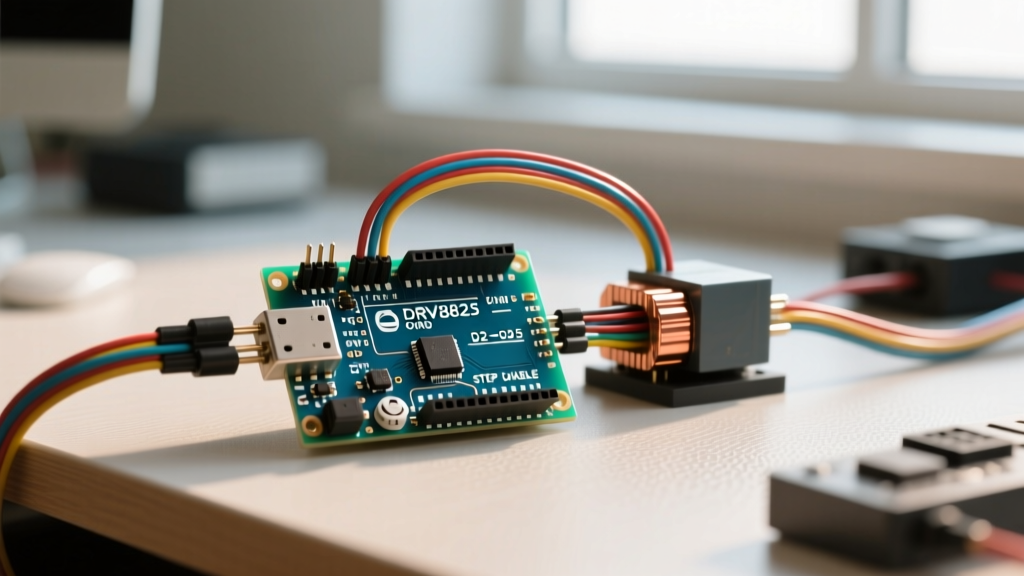
Interfacing high-torque motors with low-voltage microcontrollers is a rite of passage for electronics hobbyists. If you are attempting to connect an Arduino to a stepper driver for the first time, you are likely working with a NEMA 17 stepper motor and a chopper driver module like the A4988, DRV8825, or TMC2209. While the concept is straightforward, the physical realities of inductive loads, current limiting, and logic-level translation require precise execution.
A standard Arduino Uno R3 or Nano GPIO pin can safely source or sink only about 20mA of current. A typical NEMA 17 stepper motor requires between 1.0A and 1.7A per phase to generate its rated holding torque. Attempting to drive a motor directly from a microcontroller will instantly destroy the ATmega328P silicon. This is exactly why we use a dedicated stepper driver: it acts as a high-current, high-voltage bridge that translates low-power logic pulses into precisely timed, high-current coil energizations.
Choosing the Right Stepper Driver Module
Before making any physical connections, it is crucial to select the appropriate driver for your project's torque, noise, and budget requirements. As of 2026, the market is flooded with both genuine carrier boards and budget clones. Here is how the three most common beginner drivers compare:
| Driver IC | Max Continuous Current (w/ heatsink) | Microstepping Resolution | Avg. Price (Clone / Genuine) | Best Use Case |
|---|---|---|---|---|
| A4988 | 1.0A (1.5A peak) | Up to 1/16 | $2.50 / $8.00 | Basic CNC, low-speed 3D printer axes |
| DRV8825 | 1.5A (2.2A peak) | Up to 1/32 | $3.50 / $12.00 | Higher torque needs, medium-speed robotics |
| TMC2209 | 2.0A (2.8A peak) | Up to 1/256 (StealthChop) | $8.00 / $18.00 | Silent operation, camera sliders, precision optics |
For this tutorial, we will focus primarily on the ubiquitous A4988 stepper motor driver carrier and its pin-compatible sibling, the DRV8825, as they represent the standard baseline for learning step-dir interfacing.
The Golden Rule: The Decoupling Capacitor
Before we discuss signal wiring, we must address the most common beginner mistake that results in dead driver boards. Stepper motors are highly inductive loads. When the driver's internal MOSFETs switch off the current to a motor coil, the collapsing magnetic field generates a massive reverse voltage spike (inductive flyback).
CRITICAL WARNING: You MUST place a large electrolytic decoupling capacitor (typically 100µF) across the driver's VMOT and GND pins. This capacitor absorbs the voltage spikes. Furthermore, the capacitor's voltage rating must be at least double your power supply voltage. If you are using a 12V power supply, use a capacitor rated for 25V or 35V. If you are using a 24V supply, use a 50V rated capacitor. Failure to do this will eventually punch through the driver IC's internal dielectric, permanently shorting the chip.
Step-by-Step Wiring Guide
Wiring an Arduino to a stepper driver involves three distinct circuits: the high-power motor circuit, the low-power logic circuit, and the signal interface. Never mix these up.
1. The High-Power Motor Circuit
- VMOT: Connect to the positive terminal of your external power supply (typically 12V or 24V DC). Do NOT use the Arduino's 5V or VIN pins for this.
- GND (Power): Connect to the negative terminal of your external power supply.
- Capacitor: Solder or securely screw your 100µF capacitor directly across the VMOT and GND terminals, observing correct polarity (the stripe on the capacitor goes to GND).
- Motor Coils (1A, 1B, 2A, 2B): Connect your stepper motor wires. To identify the coils, use a multimeter in continuity mode. Two wires that show a low resistance (usually 1 to 5 ohms) belong to the same coil pair. Connect one pair to 1A/1B, and the other to 2A/2B.
2. The Logic and Signal Circuit
- VDD: Connect to the Arduino's 5V pin. This powers the internal logic and optocouplers of the driver.
- GND (Logic): Connect to one of the Arduino's GND pins. Note: The driver's logic GND and power GND are internally bridged on most carrier boards, but you must ensure a common ground reference with the Arduino.
- STEP: Connect to any digital Arduino pin (e.g., Pin 3). Every HIGH-to-LOW pulse on this pin advances the motor one microstep.
- DIR: Connect to any digital Arduino pin (e.g., Pin 4). HIGH sets one direction, LOW sets the reverse.
- ENABLE: (Optional) Connect to an Arduino pin or directly to GND. Pulling this LOW enables the driver; pulling it HIGH disables the motor coils (allowing the shaft to freewheel).
3. The Hot-Disconnect Edge Case
According to extensive hardware failure analyses documented in the Adafruit Motor Selection Guide, disconnecting the stepper motor wires while the VMOT power is active will almost instantly destroy the driver. The sudden open circuit causes an infinite voltage spike that arcs internally. Always power down the VMOT supply before plugging or unplugging motor wires.
Calibrating the Current Limit (VREF)
Out of the box, the current limit potentiometer on an A4988 or DRV8825 is set to a random factory value. If it is set too high, your motor will overheat, and the driver will trigger thermal shutdown. If it is set too low, the motor will stutter and miss steps. You must manually calibrate the VREF voltage.
Required Tools: A digital multimeter and a small ceramic flathead screwdriver (metal screwdrivers can short the potentiometer terminals to nearby components).
The A4988 VREF Formula
The current limit is determined by the voltage at the VREF test point, the internal reference multiplier, and the value of the current sense resistor ($R_s$) on the board. Most standard clone A4988 boards use a 0.1Ω sense resistor.
The formula is: Current Limit = VREF / (8 * Rs)
Therefore, to find your target VREF: VREF = Current Limit * 8 * Rs
Practical Example:
If your NEMA 17 motor is rated for 1.2A per phase, and your board has a 0.1Ω resistor:
VREF = 1.2A * 8 * 0.1 = 0.96V
How to Measure and Adjust
- Power up the Arduino (providing 5V to the driver's VDD) but leave VMOT disconnected for safety during measurement.
- Set your multimeter to DC Voltage (2V or 20V range).
- Place the black probe on the Arduino GND.
- Place the red probe gently on the metal shaft of the potentiometer or the dedicated VREF test pad.
- Turn the potentiometer slowly. Clockwise usually increases voltage; counter-clockwise decreases it.
- Stop when the multimeter reads your calculated VREF (e.g., 0.96V).
Configuring Microstepping
Microstepping divides a full motor step (usually 1.8°, or 200 steps per revolution) into smaller fractional steps. This results in smoother motion and reduced resonance, though it slightly decreases holding torque. The A4988 uses three pins (MS1, MS2, MS3) to configure this resolution.
| MS1 | MS2 | MS3 | Microstep Resolution | Steps per Revolution (1.8° Motor) |
|---|---|---|---|---|
| LOW | LOW | LOW | Full Step | 200 |
| HIGH | LOW | LOW | Half Step | 400 |
| LOW | HIGH | LOW | Quarter Step | 800 |
| HIGH | HIGH | LOW | Eighth Step | 1600 |
| HIGH | HIGH | HIGH | Sixteenth Step | 3200 |
Note: If you leave the MS pins floating (unconnected), the A4988's internal pull-down resistors will default the driver to Full Step mode. For most beginner robotics projects, 1/16th stepping (all MS pins tied to 5V) provides the best balance of smoothness and processing overhead.
Software Integration: Why AccelStepper is Mandatory
Many basic tutorials use simple digitalWrite() and delay() loops to pulse the STEP pin. While this works for blinking LEDs, it is disastrous for stepper motors. A motor cannot instantly jump from 0 RPM to 1000 RPM; the inertia of the rotor will cause it to stall and vibrate loudly. You must ramp the speed up and down.
Instead of writing complex timing algorithms from scratch, use the industry-standard AccelStepper library by Mike McCauley. It handles non-blocking acceleration, deceleration, and multi-motor coordination flawlessly.
Here is a minimal, non-blocking implementation for a 1/16th microstepped setup:
#include <AccelStepper.h>

// Define pins
const int stepPin = 3;
const int dirPin = 4;

// Initialize AccelStepper (1 = external driver with step/dir)
AccelStepper stepper(1, stepPin, dirPin);

void setup() {
  // Set maximum speed in steps per second
  // For 1/16 microstepping, 3200 steps = 1 rev/sec (60 RPM)
  stepper.setMaxSpeed(3200);

  // Set acceleration in steps per second per second
  stepper.setAcceleration(1600);

  // Move 2 full revolutions (6400 steps)
  stepper.moveTo(6400);
}

void loop() {
  // Must be called as frequently as possible
  stepper.run();
}
Troubleshooting Matrix: Edge Cases and Failures
Even with perfect wiring, environmental and mechanical factors can cause issues. Use this diagnostic matrix to solve common interfacing problems:
| Symptom | Probable Cause | Solution |
|---|---|---|
| Motor vibrates but doesn't rotate | Step pulse frequency too high for the motor's inertia; no acceleration ramp. | Reduce setMaxSpeed() or increase setAcceleration() in your code. |
| Motor spins, but misses steps under load | VREF current limit set too low; insufficient torque to overcome load. | Recalculate and increase VREF slightly. Ensure power supply can deliver adequate amperage. |
| Driver IC gets too hot to touch (>80°C) | VREF set too high; inadequate heatsink cooling; stepping rate too high. | Lower VREF. Add a forced-air fan over the heatsink. Consider upgrading to a TMC2209. |
| Motor spins in the wrong direction | DIR pin logic inverted or coil pairs swapped. | Invert the DIR logic in software, or swap the 1A/1B wires with the 2A/2B wires. |
| Erratic stepping or random direction changes | Electromagnetic interference (EMI) on the STEP/DIR wires; floating logic pins. | Keep signal wires away from motor power wires. Add 10kΩ pull-down resistors to STEP and DIR pins. |
Final Thoughts on Peripheral Interfacing
Successfully wiring an Arduino to a stepper driver bridges the gap between digital logic and physical kinetic energy. By respecting the inductive nature of the motor coils, meticulously calculating your VREF current limits, and leveraging non-blocking acceleration libraries, you ensure both the longevity of your hardware and the precision of your mechanical designs. Always double-check your decoupling capacitor polarity before applying power, and your A4988 or DRV8825 will provide thousands of hours of reliable motion control.