
Beyond LiquidCrystal.begin(): Why the Datasheet Matters
In the 2026 maker landscape, high-resolution TFTs and I2C OLEDs dominate advanced dashboards. Yet, the classic 16x2 character LCD based on the Hitachi HD44780U controller remains an undisputed staple for industrial control panels, low-cost diagnostic tools, and ruggedized DIY peripherals. A standard 16x2 module (like those from HiLetgo or Sunfounder) still costs between $3.50 and $6.00 for a 5-pack, making it economically unbeatable for simple text readouts.
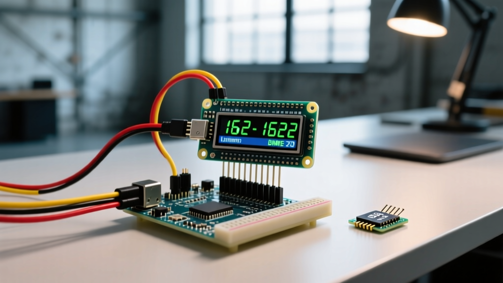
Most tutorials stop at wiring the pins and calling LiquidCrystal.begin(16, 2). But what happens when you need to design a custom PCB, optimize execution speed, or debug garbled text on a bare-metal ATmega328P? To truly master an lcd using arduino microcontrollers, you must look past the abstraction layer and decode the HD44780U datasheet. This guide breaks down the silicon-level architecture, timing diagrams, and electrical edge cases that separate amateur wiring from professional peripheral integration.
HD44780U Memory Architecture: DDRAM, CGROM, and CGRAM
The HD44780U isn't just a display; it is a microcomputer with its own internal memory. Understanding this memory map is critical for advanced cursor manipulation and custom character generation.
- DDRAM (Display Data RAM): Stores the character codes currently shown on the screen. For a 16x2 LCD, Line 1 starts at address
0x00and Line 2 starts at0x40. This 40-byte offset is a common trap: if you print 20 characters continuously without updating the cursor, the characters will wrap to hidden memory addresses before appearing on Line 2. - CGROM (Character Generator ROM): Contains the hardcoded 208 standard 5x8 dot character patterns (ASCII mapping). You cannot write to this memory.
- CGRAM (Character Generator RAM): A volatile 64-byte memory area that allows you to define up to eight custom 5x8 characters. This is essential for creating battery indicators, custom arrows, or progress bars.
Electrical Characteristics & Pinout Realities
When wiring an LCD using Arduino 5V logic (like the Uno R3 or Mega2560), the logic thresholds align perfectly with the HD44780U datasheet specifications. However, if you are interfacing with a 3.3V microcontroller (like the ESP32 or Arduino Due), you must pay strict attention to the VIH (High-level input voltage) threshold.
| Pin | Symbol | Datasheet Logic Level (VDD=5V) | Engineering Notes & Edge Cases |
|---|---|---|---|
| 3 | V0 | Analog (0V - 5V) | Sets contrast. VDD - V0 should be ~4.5V. A 1kΩ resistor to GND often replaces the standard 10kΩ potentiometer. |
| 4 | RS | VIL < 0.6V, VIH > 2.4V | Register Select. 0 = Instruction Register, 1 = Data Register. |
| 5 | RW | VIL < 0.6V, VIH > 2.4V | Read/Write. Hardwire to GND for write-only mode to save an MCU pin and avoid 5V-tolerant bus conflicts. |
| 6 | E | VIL < 0.6V, VIH > 2.4V | Enable / Clock. Triggers data latching on the falling edge. |
The V0 Contrast Hack (BOM Optimization)
The datasheet specifies that the bias voltage (VDD - V0) must be approximately 4.5V to 5.0V for standard temperature operation. Standard tutorials use a 10kΩ trimmer potentiometer. However, if you are designing a custom shield in 2026 and want to reduce BOM costs, connecting Pin 3 (V0) directly to GND through a standard 1kΩ fixed resistor yields a voltage drop that perfectly biases the liquid crystals at room temperature, eliminating the need for manual calibration.
The Critical Timing Diagrams: Enable Pulse and Execution
The most common cause of "garbled text" or "dropped characters" in bare-metal LCD programming is ignoring the datasheet's AC timing characteristics. The LCD latches data on the falling edge of the Enable (E) pin, but strict timing windows must be respected.
Datasheet Timing Specifications (VDD = 5V):
• tPW (Enable pulse width): Minimum 450ns
• tAS (Address setup time): Minimum 40ns
• tAH (Address hold time): Minimum 10ns
• tC (Enable cycle time): Minimum 1000ns (1µs)
While an Arduino Uno running at 16MHz executes a digitalWrite() command in roughly 3µs (easily satisfying the 450ns pulse width), the Execution Time of internal instructions is where developers stumble. The Clear Display command (0x01) and Return Home command (0x02) require 1.52ms to execute. If you send a character immediately after a clear command without a delayMicroseconds(1600) or checking the Busy Flag (BF), the LCD will drop the character while its internal pointer resets.
For deeper insights into how the official library abstracts these delays, refer to the Arduino LiquidCrystal Library Documentation.
The 4-Bit Initialization Sequence (The "Magic" Bytes)
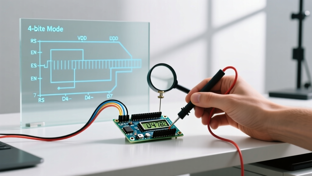
According to the HD44780U Datasheet, the controller defaults to 8-bit mode on power-up. However, because the Arduino's power-on reset circuit doesn't guarantee a clean, simultaneous voltage ramp with the LCD's internal RC oscillator, hardware initialization is unreliable. We must force a software reset into 4-bit mode using a highly specific sequence outlined on page 46 of the datasheet.
- Wait 15ms: After VCC exceeds 4.5V, wait at least 15 milliseconds for the internal logic to stabilize.
- Send 0x03 (First): Pulse the Enable pin with RS=0, RW=0, and DB4-DB7 set to 0011. Wait 4.1ms.
- Send 0x03 (Second): Repeat the exact same pulse. Wait 100µs.
- Send 0x03 (Third): Repeat again. Wait 100µs.
- Send 0x02: Set DB4-DB7 to 0010. This officially locks the controller into 4-bit mode.
Once in 4-bit mode, all subsequent commands and data bytes must be sent as two separate nibbles (high nibble first, then low nibble), each requiring its own Enable pulse.
Advanced Peripheral Control: Writing Custom Characters to CGRAM
To create custom graphics, you must manipulate the CGRAM. The HD44780 allows eight custom characters (addresses 0x00 to 0x07). Each character is an 8-byte array, where the lower 5 bits of each byte represent the pixels (1 = ON, 0 = OFF), and the top 3 bits must be zero.
Step-by-Step CGRAM Implementation
- Set the CGRAM address by sending the instruction
0x40(for character slot 0) to the Instruction Register (RS=0). - Switch to the Data Register (RS=1).
- Send the 8 bytes representing your pixel map.
- Switch back to DDRAM addressing (e.g., send
0x80to return to Line 1, Position 0). - Print the custom character by calling
lcd.write((uint8_t)0).
Note: Never use lcd.print(0) for custom characters, as the Arduino print function interprets '0' as a null terminator or integer. Always cast to uint8_t and use .write().
Troubleshooting Edge Cases & Failure Modes
Even with perfect code, physical layer issues frequently plague LCD integrations. Here are the most common failure modes observed in 2026 prototyping environments:
1. The "White Boxes" on Line 1
Symptom: Row 1 shows solid white blocks; Row 2 is blank.
Cause: The contrast voltage (V0) is incorrect, OR the initialization sequence failed, leaving the chip in an undefined 8-bit state while the MCU is sending 4-bit commands.
Fix: Verify the 15ms startup delay. Ensure your breadboard power rails aren't sagging below 4.5V under load, which corrupts the power-on reset.
2. Garbled Text Shifting Left/Right
Symptom: Characters appear, but are mixed with random Japanese/ASCII symbols and shift unpredictably.
Cause: Noise on the Enable (E) pin. Long jumper wires act as antennas, picking up EMI from nearby switching regulators or PWM motor drivers, causing the LCD to register phantom clock pulses.
Fix: Add a 100nF ceramic decoupling capacitor directly across the LCD's VDD and GND pins. Keep the Enable wire as short as possible, or add a 1kΩ pull-down resistor on the E pin to keep it firmly LOW when the MCU pin is floating during boot.
3. I2C Backpack Address Conflicts
If you are using a PCF8574 I2C backpack to save GPIO pins, remember that the default I2C address is usually 0x27 or 0x3F. Use the standard Arduino I2C Scanner sketch to verify the address before initializing your display. For a comprehensive guide on I2C peripheral integration, the Adafruit Character LCDs Tutorial provides excellent baseline schematics and pull-up resistor guidelines.
Conclusion
Building a robust lcd using arduino hardware requires more than copying example sketches. By internalizing the HD44780U datasheet—respecting the 1.52ms clear-display execution time, mastering the 4-bit software reset sequence, and optimizing the V0 bias voltage—you transform a fragile prototype into a reliable, production-ready peripheral interface.