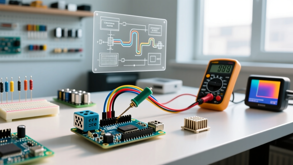

The Reality of Arduino SSR Relay Integration
Solid State Relays (SSRs) have largely replaced mechanical relays in modern DIY automation due to their silent operation, lack of moving parts, and high-speed switching capabilities. However, integrating an Arduino SSR relay circuit is rarely as simple as copying a basic wiring diagram. Whether you are using a budget-friendly Fotek SSR-25DA clone or a premium Crydom D2410, the transition from 5V DC logic to 120V/240V AC mains introduces severe edge cases. In 2026, the market remains saturated with counterfeit optocouplers and poorly potted TRIACs, making hardware-level troubleshooting an essential skill for any electronics hobbyist or prototyping engineer.
This guide bypasses generic advice and dives into the specific electrical failure modes of Arduino-driven SSRs. We will diagnose false triggering, thermal runaway, ghost loads, and zero-crossing phase errors using exact component values and real-world failure metrics.
Symptom 1: False Triggering and 'Always On' States
The most common issue when wiring an Arduino to the DC input side of an SSR (typically pins 3 and 4) is the load turning on immediately upon powering the microcontroller, or triggering randomly when nearby high-current AC devices switch.
The Floating Pin Phenomenon
During the Arduino boot sequence (which takes roughly 1.5 to 3 seconds depending on the bootloader), GPIO pins exist in a high-impedance 'floating' state. The internal optocoupler of the SSR (often a MOC3021 or MOC3063) is highly sensitive. Electromagnetic interference (EMI) from the AC mains side can induce enough voltage in the floating DC input wires to forward-bias the optocoupler's internal LED, causing the TRIAC to latch on.
- The Fix: Solder a 10kΩ pull-down resistor directly between the SSR's IN+ (or GPIO control wire) and the Arduino GND. This provides a low-impedance path for stray charges to dissipate, keeping the optocoupler firmly off until the Arduino pin is explicitly driven HIGH.
- Wiring Best Practice: Keep the DC control wires twisted and routed at least 5cm away from the AC load wires to minimize capacitive coupling.
Optocoupler LED Current Starvation
If your Arduino pin is set HIGH, but the SSR fails to trigger (or triggers intermittently), the issue is usually insufficient forward current ($I_f$). According to Electronics Tutorials, the internal LED of a standard SSR optocoupler requires a minimum of 7.5mA to 15mA to guarantee TRIAC gate activation. Many cheap SSR clones feature a poorly calculated internal current-limiting resistor designed for 12V logic. When driven by a 5V Arduino Nano or Uno, the voltage drop across the internal resistor leaves insufficient current to light the LED.
Expert Bypass: If you suspect internal current starvation, bypass the SSR's internal current-limiting resistor. Wire the Arduino GPIO through an external 220Ω resistor directly to the optocoupler's anode pin on the PCB. This guarantees ~15mA of forward current at 5V, ensuring rock-solid triggering.
Symptom 2: Catastrophic Overheating and Thermal Runaway
A frequent and dangerous failure mode is the SSR melting its plastic casing or desoldering its own output terminals. Budget SSRs like the Fotek SSR-25DA boldly claim a '25 Amp' rating on the front label. In reality, pushing 25A through a clone SSR without active cooling will result in catastrophic thermal failure in under 45 seconds.
The Physics of TRIAC Heat Dissipation
Unlike mechanical relays which have near-zero closed-contact resistance, SSRs utilize TRIACs or back-to-back SCRs. These semiconductor junctions inherently exhibit a forward voltage drop ($V_f$) of 1.2V to 1.6V when conducting. This voltage drop is converted directly into heat ($P = V_f \times I$).
If you are switching a 12A space heater, the power dissipated as heat inside the SSR is: $1.4V \times 12A = 16.8 Watts$. Without a heatsink, the thermal resistance of the SSR baseplate to ambient air is roughly 8°C/W. This means the internal junction temperature will rise by $16.8W \times 8°C/W = 134.4°C$ above room temperature. Since the maximum safe junction temperature ($T_j$) is 125°C, the SSR will thermally latch and fail.
Thermal Management Matrix (2026 Standards)
Use the table below to size your heatsink based on continuous AC load current. Always apply a thin layer of high-quality thermal compound (e.g., Arctic MX-6) between the SSR baseplate and the aluminum extrusion.
| Continuous Load Current | Heat Dissipation (Approx) | Required Thermal Solution | Recommended SSR Upgrade |
|---|---|---|---|
| 0A - 3A | ~4.2W | PCB mounting or bare metal chassis | Fotek SSR-25DA / Omron G3MB-202P |
| 3A - 8A | ~11.2W | Passive finned heatsink (min 4.0°C/W) | Omron G3NA-210B |
| 8A - 15A | ~21.0W | Large extruded heatsink (min 1.5°C/W) | Crydom D1225 |
| 15A - 30A | ~42.0W | Active fan cooling or dual-SCR panel mount | Crydom D2440 / D2450 |
Symptom 3: Leakage Current and 'Ghost' Loads
You command the Arduino to turn the SSR off, but the connected load (usually a sensitive LED driver, a small transformer, or a neon indicator lamp) remains faintly illuminated or emits a high-pitched whine. This is caused by off-state leakage current.
As detailed in the Wikipedia overview of Solid State Relays, the semiconductor junctions never provide infinite resistance when open. A standard zero-crossing SSR will leak between 1mA and 5mA at 240VAC. While 2mA is harmless to a 1000W resistive heater, it is more than enough to partially charge the input capacitors of a modern switched-mode LED power supply, causing it to strobe or glow.
The Bleeder Resistor Solution
To eliminate ghost loads, you must provide a parallel path for the leakage current to bypass the load. Solder a 120kΩ, 2-Watt metal film resistor directly across the AC output terminals (Terminals 1 and 2) of the SSR. This bleeder resistor will draw roughly 2mA of current (at 240VAC), safely absorbing the SSR's leakage current and ensuring the voltage across the actual load drops to near-zero when the SSR is off.
Symptom 4: Zero-Crossing Failures on Inductive Loads
Most standard DC-to-AC SSRs (like the SSR-25DA) are 'Zero-Crossing' types. They contain internal circuitry that waits until the AC sine wave crosses 0V before triggering the TRIAC. This minimizes inrush currents and reduces EMI. However, this feature becomes a massive liability when switching highly inductive loads like large AC motors, solenoids, or uncorrected fluorescent ballasts.
The Phase Shift Problem
In an inductive circuit, the current waveform lags behind the voltage waveform. When the AC voltage crosses zero, the current is still flowing. The SSR's internal zero-crossing detector monitors voltage, not current. When the Arduino attempts to turn the SSR off, the TRIAC cannot commutate (turn off) because the current hasn't dropped below the holding threshold yet. Conversely, when turning on, the phase shift can confuse the internal MOC optocoupler, resulting in the SSR only conducting half-cycles, sending DC-biased power to your AC motor and rapidly destroying the windings.
How to Fix Inductive Switching Failures
- Use a Random-Fire SSR: If your application requires switching inductive loads on and off rapidly, abandon zero-crossing SSRs. Purchase a 'Random Turn-On' or 'Instant-On' SSR (e.g., Crydom D1225-R). These trigger immediately upon receiving the Arduino logic signal, regardless of the sine wave position.
- Add an RC Snubber Network: If you must use a zero-crossing SSR, wire an RC snubber across the output terminals to suppress the high $dV/dt$ (rate of voltage rise) transients that cause false re-triggering. A standard snubber consists of a 100Ω resistor in series with a 0.1µF, 400VAC X2-rated film capacitor.
Diagnostic Checklist for the Workbench
Before replacing a suspected dead SSR, run through this rapid diagnostic sequence using a multimeter and your Arduino's serial monitor:
- Step 1: Verify DC Input Voltage. Measure across the SSR's DC input pins while the Arduino is HIGH. You must see at least 3V DC. If it is lower, your Arduino pin is overloaded or the internal resistor is mismatched.
- Step 2: Check the Status LED. If the SSR's built-in LED lights up but the AC load doesn't engage, the internal optocoupler is likely functional, but the TRIAC gate has failed open. The SSR is trash; replace it.
- Step 3: Measure Output Voltage. With the SSR commanded OFF, measure the AC voltage across terminals 1 and 2. You will read the full mains voltage (e.g., 120VAC) because the SSR is a switch, not a ground. When commanded ON, the voltage across 1 and 2 should drop to 1.2V - 1.6V. If it remains high, the TRIAC has failed short or isn't receiving gate current.
- Step 4: Inspect GPIO Configuration. Ensure your Arduino code explicitly sets the pin mode to
OUTPUTin thesetup()function. As noted in the official Arduino Digital Pins documentation, failing to declare the pin mode leaves it in a high-impedance state, which cannot source the required 15mA to drive the SSR optocoupler.
Final Thoughts on Component Selection
Troubleshooting an Arduino SSR relay setup often reveals that the root cause isn't the wiring, but the component quality. The $5 'Fotek' clones found on Amazon and AliExpress are notorious for using undersized silicon dies and fake potting compound that traps heat. For any project switching more than 5A, or for any load where a failure could cause a fire hazard, invest the $45-$65 required for a genuine Crydom, Omron, or Carlo Gavazzi panel-mount SSR. The upfront cost eliminates 90% of the thermal and leakage issues detailed in this guide, ensuring your 2026 automation projects run safely and reliably.