
Why Choose a ToF Laser Distance Sensor Over Ultrasonic?
When building DIY robotics or automated measurement rigs, hobbyists often default to the HC-SR04 ultrasonic module. While cheap, ultrasonic sensors suffer from a wide 15-degree acoustic beam, making them useless for precise edge detection or targeting small objects. Enter the Time-of-Flight (ToF) laser distance sensor. By emitting a focused 940nm VCSEL (Vertical-Cavity Surface-Emitting Laser) pulse and measuring the phase shift or time delay of the returning photons, ToF sensors achieve a tight 2-to-3-degree beam width and millimeter-level accuracy.
According to RP Photonics, optical time-of-flight measurements bypass the acoustic echoing issues inherent in soft or angled surfaces, providing reliable data even on sound-absorbing materials like foam or heavy fabrics. This makes them vastly superior for indoor navigation and precise liquid-level monitoring.
Sensor Selection Matrix: TF-Luna vs. TF02-Pro vs. VL53L1X
Before wiring anything, you must select the right module for your 2026 project budget and range requirements. The Benewake TF-series and STMicroelectronics VL-series dominate the maker market.
| Model | Max Range | Interface | Approx. Price (2026) | Best Application |
|---|---|---|---|---|
| Benewake TF-Luna | 8 Meters | UART / I2C | $12 - $15 | Indoor drones, desktop robotics |
| Benewake TF02-Pro | 40 Meters | UART / I2C / CAN | $45 - $60 | Outdoor rovers, industrial tank level |
| ST VL53L1X | 4 Meters | I2C Only | $10 - $14 | Precision gesture, short-range collision |
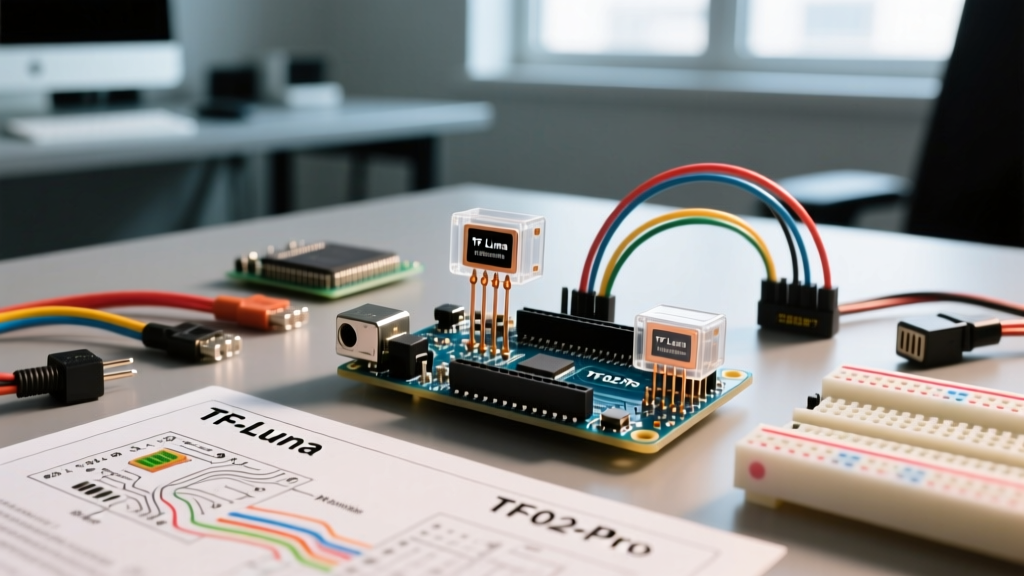
For this tutorial, we will focus on the Benewake TF-Luna, as it represents the perfect entry point for a laser distance sensor Arduino integration.
Wiring the TF-Luna to Arduino Uno (UART Mode)
The TF-Luna ships configured for UART (serial) communication at 115200 baud by default. It outputs a continuous 9-byte data frame. While wiring seems straightforward, a critical logic-level mismatch destroys more beginner sensors than any other mistake.
The 3.3V vs 5V Logic Trap
The TF-Luna operates on 5V power but uses 3.3V logic for its TX and RX pins. The Arduino Uno operates on 5V logic. If you connect the Uno's 5V TX pin directly to the TF-Luna's 3.3V RX pin, you will overvoltage and permanently damage the sensor's internal microcontroller. As detailed in the SparkFun Logic Levels guide, you must step down the voltage.
⚠️ CRITICAL WARNING: Never connect a 5V Arduino digital pin directly to a 3.3V sensor RX pin without a logic level converter or a voltage divider.
Step-by-Step Wiring Guide
- Power: Connect the TF-Luna Red wire to the Arduino 5V pin, and the Black wire to GND.
- Sensor TX to Arduino RX: Connect the TF-Luna Green (TX) wire directly to Arduino Pin 10 (SoftwareSerial RX). The 3.3V output from the sensor is safely recognized as a HIGH signal by the 5V Uno.
- Arduino TX to Sensor RX (Voltage Divider): Use a simple resistor voltage divider. Connect a 1kΩ resistor from Arduino Pin 11 (TX) to the junction point. Connect a 2kΩ resistor from the junction point to GND. Connect the junction point to the TF-Luna White (RX) wire. This drops the 5V signal down to a safe ~3.3V.
Arduino Code for UART Interfacing
To read the data, we use the Arduino SoftwareSerial library, which allows us to create a secondary serial port on digital pins, leaving the hardware serial (pins 0 and 1) free for debugging via the Serial Monitor.
#include <SoftwareSerial.h>

// Define software serial pins: RX = 10, TX = 11
SoftwareSerial tfLunaSerial(10, 11);

int dist;      // Distance value
int strength;  // Signal strength
uint8_t check; // Checksum
uint8_t rx[9]; // 9-byte data frame

void setup() {
  Serial.begin(115200);      // Hardware serial for monitor
  tfLunaSerial.begin(115200); // Software serial for sensor
}

void loop() {
  if (tfLunaSerial.available()) {
    if (tfLunaSerial.read() == 0x59) { // Check for first header byte
      rx[0] = 0x59;
      if (tfLunaSerial.read() == 0x59) { // Check for second header byte
        rx[1] = 0x59;
        for (int i = 2; i < 9; i++) {
          // Wait for remaining bytes with a timeout
          unsigned long t = millis();
          while (!tfLunaSerial.available()) {
            if (millis() - t > 10) return;
          }
          rx[i] = tfLunaSerial.read();
        }

        // Calculate Checksum
        check = 0;
        for (int i = 0; i < 8; i++) check += rx[i];

        if (rx[8] == check) { // Verify checksum
          dist = rx[2] + (rx[3] << 8);
          strength = rx[4] + (rx[5] << 8);
          Serial.print("Distance: ");
          Serial.print(dist);
          Serial.print(" cm | Strength: ");
          Serial.println(strength);
        }
      }
    }
  }
}
Protocol Deep Dive: UART vs. I2C Interfacing
Out of the box, the TF-Luna and TF02-Pro default to UART communication. However, both support I2C if you send the appropriate configuration hex commands via a USB-to-serial adapter. Why would you switch?
UART Advantages: Point-to-point simplicity. It requires minimal code overhead and doesn't suffer from bus capacitance issues over longer wire runs. If you are wiring a single sensor to an Arduino Uno, stick to UART.
I2C Advantages: Bus topology. I2C allows you to daisy-chain multiple sensors on the same two wires (SDA/SCL), provided each sensor has a unique I2C address. The TF-Luna's default I2C address is 0x10. If you need three sensors for a triangulation rover, I2C saves digital I/O pins, though you must ensure your total wire length stays under 30cm to prevent signal degradation without external pull-up resistors.
Real-World Failure Modes and Edge Cases
Building a circuit on a desk is easy; deploying it in the real world introduces optical physics challenges. Here are the specific failure modes you must engineer around:
- Sunlight Saturation (SNR Drop): The 940nm VCSEL laser competes with infrared radiation from the sun. Outdoors, the TF-Luna's maximum reliable range drops from 8 meters to roughly 1.5 meters. Fix: Use the TF02-Pro for outdoor projects, or 3D print a narrow, matte-black shroud (snoot) around the sensor aperture to block peripheral ambient IR.
- Specular Reflections: ToF sensors require diffuse reflection to bounce photons back to the receiver. If you point the TF-Luna at a mirror, glass window, or highly polished metal at an angle greater than 10 degrees, the laser beam will deflect away, resulting in a "Signal Strength: 0" error or a false maximum-distance reading.
- Minimum Blind Zone: The TF-Luna has a physical blind zone of 10 cm due to the internal spatial separation between the emitter and receiver lenses. Objects closer than 10 cm will either return erratic data or output a flat 12 cm reading. If your robot needs sub-5 cm collision detection, you must pair the ToF sensor with a short-range IR proximity sensor like the Sharp GP2Y0A21YK0F.
Pro Tips for 2026 Enclosures and Mounting
When designing your final 3D-printed or CNC-machined enclosure, do not leave the sensor optics exposed to dust and fingerprints. Skin oils on the lens will scatter the 940nm beam, drastically reducing signal strength. Instead, cover the aperture with IR-pass visible-block acrylic (often sold as "night vision camera filters" or 850nm/940nm pass filters). This material looks completely opaque black to the human eye but allows the near-infrared laser to pass through with over 90% transmission efficiency, keeping your optics pristine in harsh environments.