
The Multi-Peripheral Challenge in Piezo Acoustic Detection
Integrating a piezo sensor Arduino setup is a staple of DIY electronics, often used for knock-detection locks, electronic drums, or vibration alarms. However, reading a high-impedance analog piezoelectric signal becomes significantly more complex when you introduce multiple peripherals to the same microcontroller bus. When you add an I2C OLED display for user feedback, a high-torque servo motor for the physical locking mechanism, and an active buzzer, the ATmega328P’s Analog-to-Digital Converter (ADC) is frequently flooded with electromagnetic interference (EMI) and voltage sags.
This guide details the exact hardware signal conditioning, power rail isolation, and non-blocking firmware architecture required to build a reliable, multi-peripheral knock-activated smart lock in 2026, ensuring your ADC readings remain pristine even while a servo is actively drawing peak stall current.
Bill of Materials (2026 Component Pricing)
To replicate this high-reliability setup, avoid generic "piezo buzzer" modules that include built-in oscillator boards. You need a raw piezoelectric ceramic element. Below is the verified BOM with current market pricing.
| Component | Specific Model / Part Number | Function | Est. Price (USD) |
|---|---|---|---|
| Piezo Element | Murata 7BB-27-4L0 (27mm) | Acoustic/Vibration Transducer | $2.85 |
| Microcontroller | Arduino Nano Every (ATmega4809) | Main Logic & ADC Processing | $20.00 |
| Display | SSD1306 128x64 I2C OLED (0x3C) | Visual Feedback & State UI | $7.50 |
| Actuator | Tower Pro SG90 or MG90S (Metal Gear) | Physical Deadbolt Actuation | $4.50 |
| Signal Conditioning | 1MΩ Resistor, 1N4148 Diode, 5.1V Zener | ADC Protection & Bleed | $0.15 |
| Power Isolation | LM2596 Buck Converter (Set to 5.1V) | Dedicated Servo Power Rail | $3.20 |
Hardware Signal Conditioning: Protecting the ADC
A common failure mode in beginner piezo circuits is frying the microcontroller's analog pin. According to the SparkFun Piezo Vibration Sensor Hookup Guide, a sharp mechanical impact on a 27mm piezo ceramic can generate voltage spikes exceeding 50V. The ATmega4809 on the Nano Every will suffer permanent silicon damage if an analog pin exceeds VCC + 0.5V.
⚠️ Critical Warning: Never wire a raw piezo element directly to an Arduino analog pin. The internal ESD protection diodes will conduct, but sustained high-energy knocks will overload the internal trace limits, leading to a shorted ADC channel.
The Clamping and Bleed Circuit
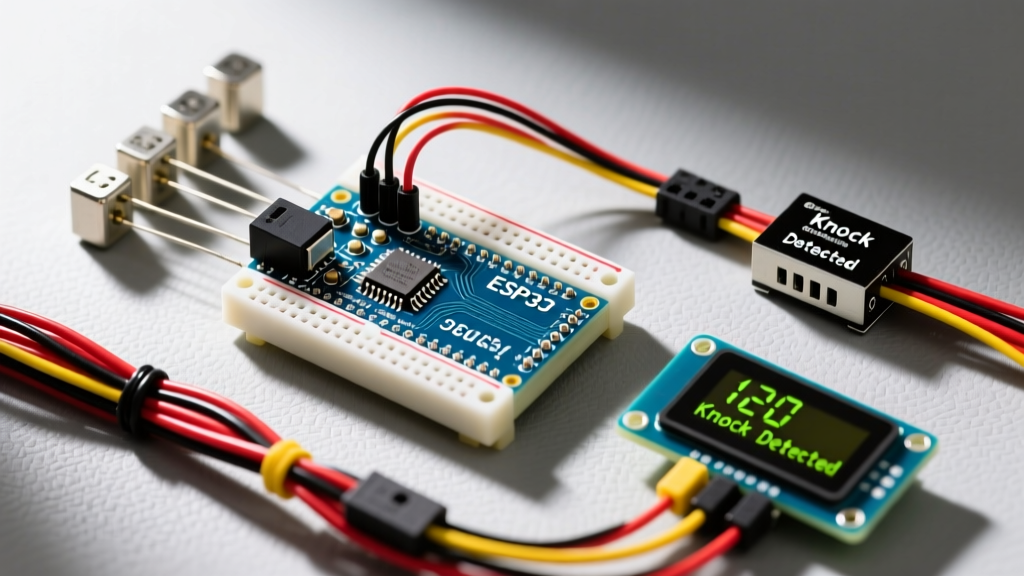
To safely interface the Murata 7BB-27-4L0, you must construct a parallel conditioning network directly at the sensor's solder pads:
- 1MΩ Bleed Resistor: Placed in parallel with the piezo. Piezo elements act as capacitors (typically ~15nF for a 27mm disc). Without a discharge path, a single knock will charge the element, and the voltage will linger, causing the Arduino to register a continuous "high" state. The 1MΩ resistor creates an RC time constant that dissipates the charge within milliseconds.
- 5.1V Zener Diode: Placed in reverse bias between the signal line and ground. This clamps any voltage spike above 5.1V, safely shunting the excess kinetic energy to ground before it reaches the A0 pin.
- 1N4148 Signal Diode: Placed in series with the signal line (anode to piezo, cathode to Arduino A0) to block negative voltage swings that occur when the piezo flexes in the opposite direction.
Mechanical Coupling: The Hidden Variable
Electrical engineers often overlook mechanical resonance. How you mount the piezo dictates its voltage output. If you use cyanoacrylate (Super Glue), the brittle bond dampens high-frequency vibrations. Hot glue is even worse, acting as a shock absorber that can reduce peak voltage output by up to 60%. For optimal kinetic transfer to the ceramic lattice, mount the piezo to the interior of your project enclosure using 3M VHB 4910 double-sided acrylic tape. This provides a rigid yet slightly compliant bond that maximizes acoustic transfer while surviving thermal expansion cycles.
Power Rail Isolation for Multi-Peripheral Setups
When the SG90 servo actuates the lock, it draws a stall current of roughly 700mA. If powered directly from the Arduino Nano's 5V pin (which is fed by the onboard linear regulator or USB), this current spike causes a massive voltage sag. This sag manifests as two distinct failures:
- ADC Noise: The analog reference voltage (VREF) drops, causing the piezo sensor's baseline reading to jitter wildly.
- I2C Bus Crashes: The SSD1306 OLED display requires a stable 3.3V/5V logic level. A brownout will corrupt the I2C clock line (SCL), freezing the display or causing the Arduino to hang in a Wire.h infinite loop.
The UBEC / Buck Converter Solution
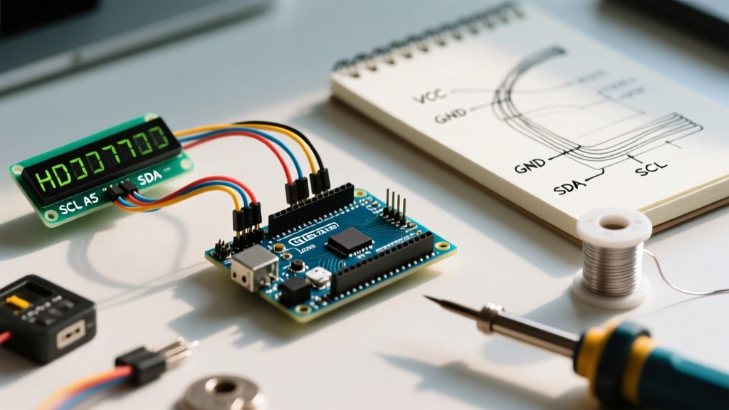
Do not share the Arduino's 5V rail with the servo. Instead, use an external 7-12V power supply connected to an LM2596 buck converter stepped down to exactly 5.1V. Wire the servo's red power lead to this dedicated 5.1V rail. Crucially, you must tie the ground of the buck converter to the Arduino's GND pin to establish a common reference for the PWM control signal on Digital Pin 9.
Non-Blocking Firmware Architecture
Reading a piezo sensor requires fast, sequential polling to detect the distinct intervals of a multi-knock pattern (e.g., Knock... Knock-Knock). If your code uses delay() to refresh the OLED display or wait for the servo to reach its target angle, you will miss the analog spike of the second knock. The official Arduino analogRead() documentation notes that a single conversion takes approximately 100 microseconds, meaning you can theoretically sample 10,000 times per second, but blocking code ruins this throughput.
Implementing a Time-Sliced State Machine
To handle the OLED, Servo, and Piezo simultaneously, implement a millis()-based state machine. Below is the architectural logic for the knock-recording array:
unsigned long knockTimes[5];
int knockCount = 0;
unsigned long lastKnockTime = 0;
const int KNOCK_THRESHOLD = 150; // Calibrated for VHB tape mounting
const int KNOCK_TIMEOUT = 1500;  // 1.5 seconds to complete pattern

void loop() {
  int piezoVal = analogRead(A0);
  unsigned long currentMillis = millis();

  // 1. Non-blocking Piezo Polling
  if (piezoVal > KNOCK_THRESHOLD && (currentMillis - lastKnockTime) > 100) {
    if (knockCount < 5) {
      knockTimes[knockCount] = currentMillis;
      knockCount++;
      lastKnockTime = currentMillis;
    }
  }

  // 2. Pattern Evaluation & Timeout Reset
  if (knockCount > 0 && (currentMillis - knockTimes[0]) > KNOCK_TIMEOUT) {
    evaluateKnockPattern();
    knockCount = 0; // Reset array
  }

  // 3. Non-blocking OLED & Servo updates run here
  updateOLEDState(currentMillis);
  actuateServoIfNeeded(currentMillis);
}
By decoupling the sensor polling from the UI rendering, the microcontroller can refresh the SSD1306 OLED display via I2C every 250ms while still checking the piezo ADC every single loop iteration (typically under 2ms).
Troubleshooting Matrix: Edge Cases & Failure Modes
Even with perfect wiring, environmental factors can disrupt piezo acoustic detection. Use this diagnostic matrix to resolve erratic behavior.
| Symptom | Root Cause Analysis | Engineer's Fix |
|---|---|---|
| "Ghost" knocks triggered by closing a nearby door. | Low-frequency acoustic resonance traveling through the enclosure walls. | Implement a software high-pass filter. Require the ADC delta to cross the threshold within a 15ms window to qualify as a sharp "tap" rather than a slow "rumble". |
| Servo jitters violently when OLED updates. | I2C bus capacitance and OLED current draw creating ground bounce on the PWM line. | Add a 470µF electrolytic capacitor directly across the servo's power pins, and route the PWM signal through a 220Ω series resistor to dampen ringing. |
| ADC reads floating values (e.g., jumping 12 to 45) when untouched. | High-impedance analog pin acting as an antenna for 50/60Hz mains hum. | Lower the bleed resistor from 1MΩ to 330kΩ. This decreases the RC time constant, making the pin less sensitive to ambient electromagnetic fields at the cost of slight sensitivity loss. |
| First knock registers, subsequent knocks in a sequence fail. | Piezo element has not fully discharged before the second physical impact occurs. | Check the 1MΩ resistor solder joints. If using a smaller piezo (e.g., 12mm), increase the resistor to 2.2MΩ as smaller ceramics have lower capacitance and discharge too quickly for the ADC to catch the peak. |
Final Calibration Steps
Before sealing your enclosure, use the Arduino IDE Serial Plotter at 115200 baud to visualize the raw analog data. Tap the enclosure with varying force using a wooden dowel. Set your KNOCK_THRESHOLD variable exactly 30% above the highest ambient noise floor recorded during a 60-second idle test, but at least 40% below your lightest intentional knock. This guarantees a robust signal-to-noise ratio (SNR) for long-term deployment.