
The Challenge of Multi-Peripheral Stepper Integration
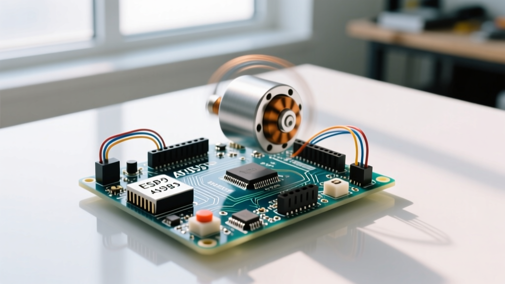
When building automated camera sliders, CNC plotters, or precision fluid dispensers, controlling a stepper motor with Arduino is rarely a standalone task. In real-world engineering, your microcontroller must simultaneously manage the motor driver, poll limit switches, read a rotary encoder for manual jogging, and update an I2C OLED display with real-time telemetry.
This multi-peripheral environment introduces severe bottlenecks. Pin conflicts, Electromagnetic Interference (EMI) from stepper coils, and timing delays can cause missed steps, frozen displays, and ghost encoder inputs. This guide details the exact hardware architecture, power distribution strategies, and non-blocking firmware patterns required to reliably integrate a NEMA 17 stepper motor alongside complex I2C and interrupt-driven peripherals in 2026.
Hardware BOM: The 2026 Standard for Complex Rigs
To handle concurrent peripheral polling and high-frequency step pulsing, we recommend moving past the legacy 16MHz ATmega328P. Here is the optimized bill of materials for a robust multi-peripheral build:
- MCU: Arduino Uno R4 Minima (~$20). The 48MHz Renesas RA4M1 processor natively supports FreeRTOS and handles I2C bus recovery far better than older AVR chips.
- Motor: NEMA 17 Bipolar Stepper (e.g., StepperOnline 17HS19-2004S1, 2A/phase, 59N·cm torque) (~$14).
- Driver: Texas Instruments DRV8825 carrier board (~$4). Supports up to 45V and 1/32 microstepping, offering much smoother operation than the older A4988.
- Display: 0.96-inch SSD1306 I2C OLED (128x64) (~$6).
- Input: EC11 Rotary Encoder with integrated pushbutton (~$2).
- Power: LM2596 Buck Converter module and a 24V 5A switching power supply (~$15 total).
Power Distribution: Avoiding the 5V Rail Bottleneck
The most common failure mode when controlling a stepper motor with Arduino in a multi-peripheral setup is a brownout reset. Stepper motors generate massive back-EMF and voltage spikes during coil de-energization. If you share the Arduino's onboard 5V regulator with the motor logic, the voltage ripple will corrupt I2C data packets and reset the MCU.
⚠️ Critical Power Rule: Never power the DRV8825 VMOT pin from the same 5V rail as your I2C OLED or Arduino logic. Use a dedicated 24V supply for the motor, and an LM2596 buck converter to step down 24V to a clean 5V for the Arduino and peripherals.Setting the DRV8825 Current Limit
Before wiring the peripherals, you must calibrate the driver's current limit to prevent the NEMA 17 from overheating and skipping steps. For standard DRV8825 carriers with 0.1Ω sense resistors, the formula is Vref = Imax / 2. If your motor is rated for 2A, you should run it at 75% capacity (1.5A) for continuous duty. Therefore, adjust the trimpot until the Vref test point reads 0.75V.
Pin Mapping Matrix: Resolving Conflicts
Integrating an encoder, OLED, and stepper driver requires careful pin allocation to avoid hardware interrupt clashes. The Uno R4 Minima has dedicated interrupt pins that we must map correctly.
| Peripheral | Driver/Sensor Pin | Arduino Uno R4 Pin | Notes |
|---|---|---|---|
| DRV8825 | STEP | D3 (PWM) | High-frequency pulse output |
| DRV8825 | DIR | D4 | Digital HIGH/LOW |
| DRV8825 | ENABLE | D5 | Active LOW to release coils |
| SSD1306 OLED | SDA / SCL | A4 / A5 | Hardware I2C bus |
| EC11 Encoder | CLK / DT | D2 / D6 | D2 is hardware interrupt 0 |
Non-Blocking Firmware: Ditching the Delay Function
If you use delay() to time your stepper pulses, your I2C OLED will freeze, and your rotary encoder will miss clicks. To successfully manage multiple peripherals, you must use the AccelStepper library alongside a millis()-based state machine.
AccelStepper handles the complex acceleration and deceleration ramping in the background. By calling stepper.run() inside the main loop(), the library evaluates whether a step pulse is due based on the current time, taking only microseconds. This leaves the rest of the loop free to poll the I2C display and read the encoder.
Expert Tip: When using AccelStepper with an I2C OLED, avoid updating the display on every single loop iteration. I2C transactions at 400kHz take roughly 2-3 milliseconds. Update the OLED only when the motor position changes by a meaningful threshold, or use a non-blocking timer to refresh the screen exactly every 100ms.
EMI and I2C Bus Capacitance: The Silent Killers
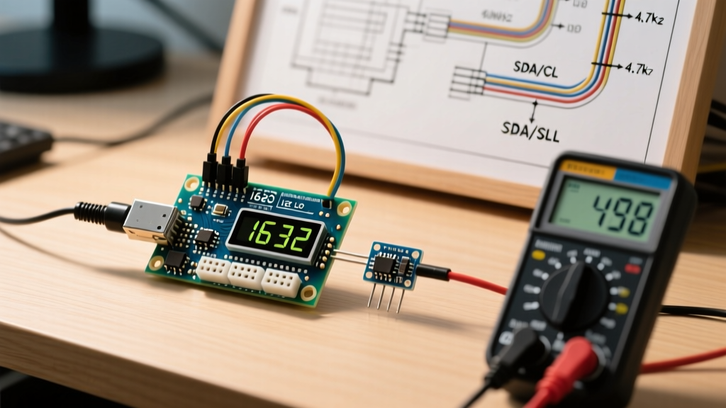
Stepper motor cables act as high-power antennas, radiating EMI that can easily corrupt the sensitive, low-voltage I2C bus used by your OLED and sensors. Furthermore, long I2C wires increase bus capacitance, degrading the square wave signals.
According to Analog Devices' I2C Primer, the maximum allowed bus capacitance is 400pF. In a multi-peripheral rig with long cable runs, you will often exceed this, resulting in corrupted OLED pixels or complete bus lockups.
Mitigation Strategies
- Physical Separation: Route I2C and encoder signal wires at least 2 inches away from the stepper motor coil wires. Never bundle them in the same cable sleeve.
- Twisted Pairs: Use twisted pair cabling for the stepper motor coils to cancel out the magnetic field radiation.
- Pull-Up Resistor Tuning: The standard 4.7kΩ I2C pull-up resistors are too weak for high-capacitance buses. Solder 2.2kΩ or even 1kΩ pull-up resistors to the SDA and SCL lines to provide sharper rising edges and reject EMI noise.
Troubleshooting Missed Steps and Stalls
Even with perfect code, hardware anomalies occur. Here is how to diagnose the most common multi-peripheral stepper failures:
- Symptom: Motor stalls and hums when the OLED updates.
Cause: I2C blocking code is delaying the STEP pulse beyond the motor's pull-in torque threshold.
Fix: Ensure you are usingstepper.run()and notstepper.runToPosition(), which blocks the main loop until the move is complete. - Symptom: Ghost encoder clicks (registering multiple steps per physical detent).
Cause: EMI from the stepper driver is inducing voltage spikes on the encoder data lines.
Fix: Add 0.1µF ceramic decoupling capacitors between the encoder CLK/DT pins and GND, directly at the Arduino header. - Symptom: Motor loses position over long runs.
Cause: Insufficient current limit or lack of microstepping causing resonance.
Fix: Re-verify the Vref voltage on the DRV8825 and ensure the MODE0, MODE1, and MODE2 pins are pulled HIGH for 1/16 microstepping, which drastically reduces mid-band resonance.
By treating power isolation, non-blocking firmware, and EMI mitigation as first-class design requirements, you can reliably scale your Arduino stepper projects from simple single-axis tests to robust, multi-peripheral automation systems.