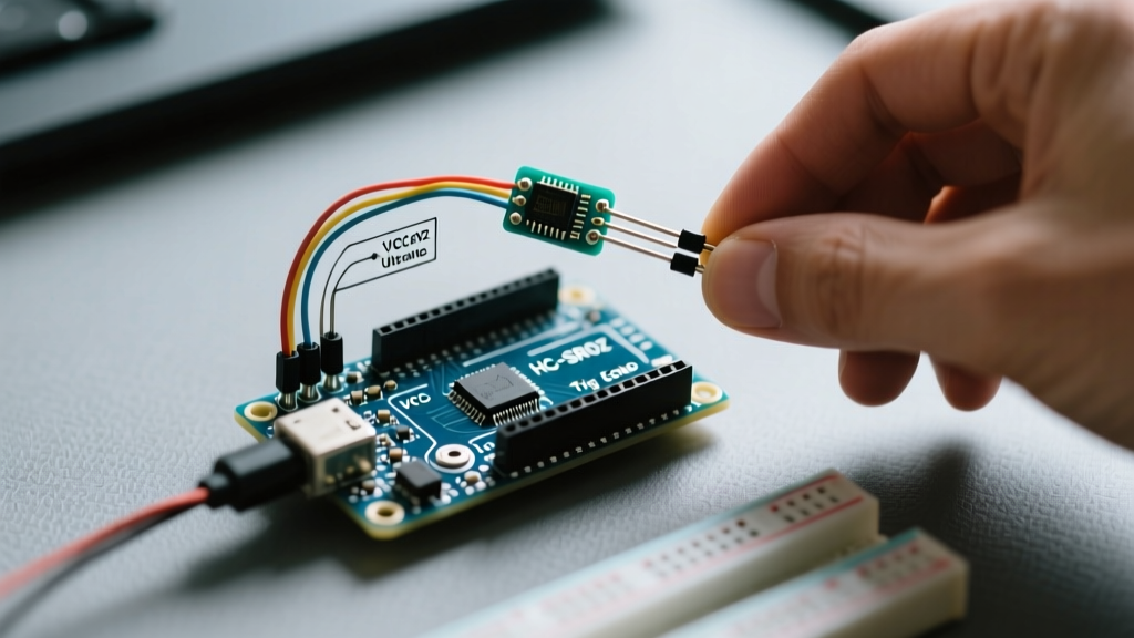

When integrating an ultra sonic sensor Arduino setup, makers and engineers frequently encounter phantom readings, zero-distance lockups, or complete microcontroller brownouts. The ubiquitous HC-SR04 and its modern variants remain the default choice for proximity detection, robotics navigation, and fluid-level monitoring in 2026. However, their deceptively simple 4-pin interface hides several hardware and software traps that generic tutorials fail to address.
This guide bypasses basic wiring diagrams and dives directly into the exact failure modes, timing bottlenecks, and acoustic anomalies that plague ultrasonic projects. Whether you are using a classic Arduino Uno R3, an ESP32-S3, or a Raspberry Pi Pico, these troubleshooting protocols will help you isolate and resolve sensor faults.
The 5V vs 3.3V Logic Level Trap
The most catastrophic and common failure mode in modern ultra sonic sensor Arduino projects occurs when interfacing 5V sensors with 3.3V microcontrollers. The standard HC-SR04 operates at 5V and outputs a 5V HIGH signal on the Echo pin. If you connect this directly to the GPIO of an ESP32, RP2040, or Arduino Nano 33 IoT, you will likely fry the MCU's input pin or cause erratic system reboots due to overvoltage injection.
The Voltage Divider Solution
To safely step down the 5V Echo signal to a 3.3V logic level, use a simple resistor voltage divider. A combination of a 1kΩ resistor (R1) in series with the Echo pin and a 2kΩ resistor (R2) to ground will yield approximately 3.33V.
Pro Tip: Avoid using high-value resistors (e.g., 10kΩ/20kΩ) for the voltage divider. The Echo pin's rise time can become too slow, causing the microcontroller to miss the precise microsecond timing required for accurate distance calculations. Stick to 1kΩ/2kΩ or use a dedicated logic level shifter like the BSS138 MOSFET module for high-speed edge preservation.
Software Bottlenecks: The pulseIn() Blocking Hazard
Most beginner tutorials rely on the native pulseIn() function to measure the Echo pin's HIGH duration. However, if the ultrasonic pulse scatters and never returns, pulseIn() will block the main loop until its default timeout expires. According to the official Arduino pulseIn() documentation, the default timeout is 1 second (1,000,000 microseconds). In a robotics application, a 1-second CPU freeze can cause a robot to crash or a PID control loop to destabilize.
Fixing the Timeout
Always explicitly define a timeout value based on your maximum required detection distance. Sound travels at roughly 343 meters per second. To measure up to 4 meters (round trip of 8 meters), the maximum pulse duration is approximately 23,300 microseconds. Set your timeout to 25000:
duration = pulseIn(echoPin, HIGH, 25000);
The NewPing Library Advantage
For production-level code, abandon pulseIn() entirely. The NewPing library utilizes hardware timers and interrupts to measure pulse width without blocking the main thread. It also includes built-in median filtering to discard acoustic outliers, drastically improving reliability in noisy environments.
Hardware Triage: A 4-Step Diagnostic Flow
If your sensor is returning constant zeros, maximum distances, or random fluctuating numbers, follow this systematic hardware triage:
- Verify Power Rail Stability: The HC-SR04 draws a brief spike of ~15mA to 20mA during the 40kHz burst. Cheap breadboard power rails often suffer from voltage sag. Measure the VCC pin with an oscilloscope or multisecond-averaging multimeter during a ping. If it drops below 4.5V, add a 100µF decoupling capacitor directly across the sensor's VCC and GND pins.
- Check the Trigger Pulse Width: The sensor requires a minimum 10µs HIGH pulse on the Trigger pin to initiate a measurement. If your MCU is heavily loaded with interrupts, the
delayMicroseconds(10)command might be stretched or compressed. Use an oscilloscope to verify a clean 10µs to 15µs square wave. - Inspect the Transducer Mesh: Physical damage to the aluminum mesh covering the piezoelectric transducers will alter the acoustic impedance. If the mesh is dented or clogged with dust/solder flux, the 40kHz waves will diffract unpredictably.
- Test the Crystal Oscillator: Clone HC-SR04 modules manufactured with substandard components often use poorly calibrated ceramic resonators instead of quartz crystals. This causes the internal timing to drift, resulting in distance calculations that are consistently off by 5% to 10%. If your readings are consistently scaled wrong, replace the module with a genuine unit.
Acoustic Interference and Environmental Edge Cases
Ultrasonic sensors do not emit a tight laser beam; they broadcast a conical wave. Understanding the physics of high-frequency acoustics is critical for diagnosing phantom readings.
- The 15-Degree Beam Angle: The standard HC-SR04 has a beam angle of roughly 15 degrees. If you mount the sensor too close to the floor or a adjacent wall, the acoustic cone will reflect off the peripheral surface, returning a shorter distance than the actual target straight ahead.
- Soft Target Absorption: 40kHz sound waves are easily absorbed by porous, soft materials like acoustic foam, heavy fabrics, or fiberglass insulation. If your robot fails to detect a couch or a curtain, the material is absorbing the ping rather than reflecting it.
- Specular Reflection (Angled Surfaces): If the target surface is smooth and angled greater than 15 degrees away from the sensor's perpendicular axis, the sound wave will deflect away like light off a mirror, resulting in a 'no echo' timeout.
2026 Ultrasonic Sensor Comparison Matrix
Choosing the wrong sensor variant for your specific environment is a primary cause of project failure. Below is a comparison of the most common modules available on the market today.
| Model | Logic Voltage | Max Range | IP Rating | Avg Price (2026) | Best Use Case |
|---|---|---|---|---|---|
| HC-SR04 | 5V Only | 400 cm | None | $1.50 - $2.50 | Indoor robotics, basic Arduino Uno projects |
| HC-SR04P | 3.3V - 5V | 400 cm | None | $2.00 - $3.00 | ESP32 / RP2040 direct integration (No divider needed) |
| JSN-SR04T | 5V Only | 450 cm | IP67 (Probe) | $6.00 - $9.00 | Water tank level monitoring, outdoor automotive |
| RCWL-1601 | 3.3V - 5V | 300 cm | None | $2.50 - $3.50 | High-accuracy I2C/UART multi-sensor arrays |
Advanced Multi-Sensor Cross-Talk Mitigation
When deploying multiple ultra sonic sensor Arduino setups on a single chassis (e.g., a 4-sensor parking assist system), cross-talk becomes a severe issue. Sensor A's receiver will pick up the 40kHz echo from Sensor B, calculating a falsely short distance.
The Sequential Polling Fix: Never fire multiple sensors simultaneously. You must poll them sequentially with a mandatory delay between pings. The acoustic energy from a previous ping must be allowed to dissipate completely. A minimum delay of 35 milliseconds between firing Sensor 1 and Sensor 2 is required to prevent ghost echoes. If your application requires faster refresh rates, consider switching to Time-of-Flight (ToF) LiDAR sensors like the VL53L1X, which use infrared light and are immune to acoustic cross-talk.
Summary
Troubleshooting an ultra sonic sensor Arduino circuit requires looking beyond basic wiring. By managing 3.3V logic thresholds, eliminating pulseIn() blocking hazards, and accounting for the physical realities of 40kHz acoustic wave propagation, you can transform an unreliable hobbyist module into a robust, industrial-grade proximity system.