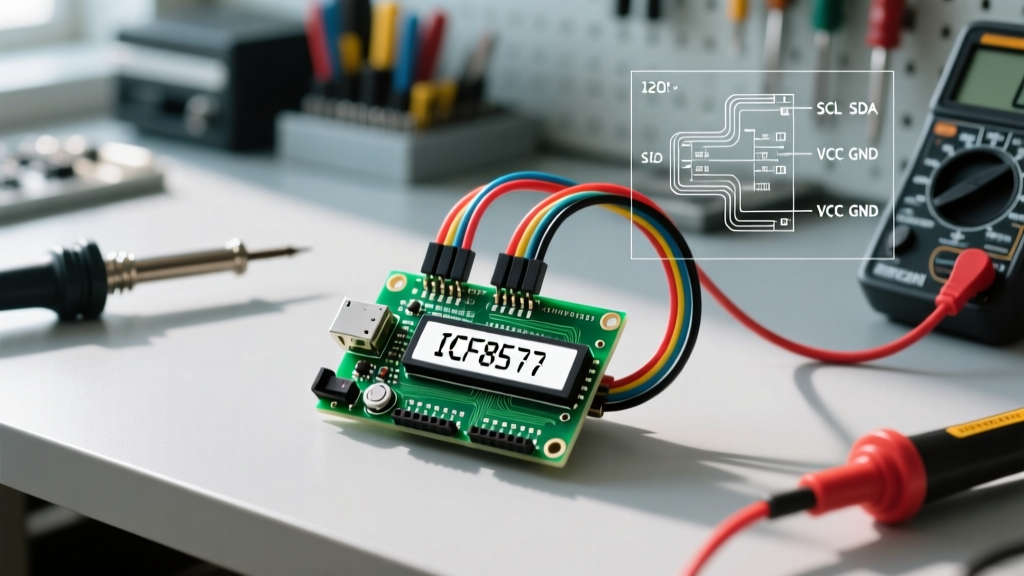

Why Choose an I2C Backpack for HD44780 Displays?
Integrating a standard 16x2 or 20x4 character LCD into a microcontroller project traditionally requires wiring up to six digital pins in 4-bit parallel mode. For complex builds involving multiple sensors, this pin consumption is a major bottleneck. The Arduino I2C LCD configuration solves this by utilizing a PCF8574 or PCF8574A I/O expander backpack, reducing the interface to just two shared pins: SDA (Serial Data) and SCL (Serial Clock).
As of 2026, the I2C backpack is the undisputed standard for hobbyist and prototyping LCD integration. It not only preserves precious GPIO pins but also simplifies cable management and allows multiple displays to share the same I2C bus (provided their addresses differ).
Parallel vs. I2C LCD Integration
| Feature | Standard Parallel (4-bit) | I2C Backpack (PCF8574) |
|---|---|---|
| GPIO Pins Required | 6 (RS, EN, D4, D5, D6, D7) | 2 (SDA, SCL) |
| Wiring Complexity | High (prone to miswiring) | Low (4 wires total) |
| Bus Sharing | Not possible | Yes (up to 8+ devices) |
| Avg. Module Cost (2026) | $3.00 (LCD only) | $4.50 (LCD + Backpack) |
Bill of Materials & Hardware Specifications
To follow this guide, you will need the following components. Pricing reflects average 2026 market rates from major electronics distributors and Amazon.
- Microcontroller: Arduino Uno R3, Nano, or compatible clone (~$22.00 - $27.00).
- Display Module: 1602 (16x2) or 2004 (20x4) LCD with HD44780 controller and pre-soldered I2C backpack (~$4.50 - $6.50).
- Wiring: 4x Female-to-Male Dupont jumper wires.
- Optional but Recommended: 2x 4.7kΩ pull-up resistors (for bus stability on longer wire runs).
Step-by-Step Wiring Diagram & Pinout
The I2C backpack features four primary pins: GND, VCC, SDA, and SCL. Wiring is straightforward, but you must pay strict attention to the logic voltage levels. Most standard Arduino boards (Uno, Mega, Nano) operate at 5V logic, which matches the LCD backpack perfectly. However, if you are adapting this guide for 3.3V boards (like the ESP32 or Arduino Nano 33 IoT), you must use a logic level shifter to prevent damaging the PCF8574 chip or experiencing ghost characters.
Standard Arduino Uno / Nano Wiring Table
| Backpack Pin | Arduino Uno / Nano Pin | Function |
|---|---|---|
| GND | GND | Common Ground Reference |
| VCC | 5V | Power Supply (Requires ~80mA) |
| SDA | A4 (or dedicated SDA pin) | I2C Serial Data Line |
| SCL | A5 (or dedicated SCL pin) | I2C Serial Clock Line |
Expert Note on Power Delivery: The backlight LED array on a 20x4 LCD can draw upwards of 120mA. While the Arduino's onboard 5V regulator can handle this, it will generate noticeable heat. For 20x4 displays or multiple LCDs, power the VCC line directly from an external 5V buck converter, ensuring a common ground with the Arduino.
Solving the I2C Address Mystery (0x27 vs 0x3F)
The single most common failure mode when setting up an Arduino I2C LCD is using the wrong I2C address. Manufacturers use two primary variants of the I/O expander chip:
- PCF8574T (NXP/TI): Typically defaults to hex address
0x27. - PCF8574AT (NXP/TI): Typically defaults to hex address
0x3F.
According to the Texas Instruments PCF8574 Datasheet, the address is dictated by the A0, A1, and A2 jumper pads on the backpack. Before writing your main application code, you should always run an I2C Scanner sketch to definitively identify the address. You can find the official scanner in the Arduino IDE under File > Examples > Wire > i2c_scanner, or use the snippet below:
#include <Wire.h>

void setup() {
  Wire.begin();
  Serial.begin(115200);
  while (!Serial); // Wait for serial monitor
  Serial.println("\nI2C Scanner");
}

void loop() {
  int nDevices = 0;
  for (byte address = 1; address < 127; address++) {
    Wire.beginTransmission(address);
    byte error = Wire.endTransmission();
    if (error == 0) {
      Serial.print("I2C device found at address 0x");
      if (address < 16) Serial.print("0");
      Serial.println(address, HEX);
      nDevices++;
    }
  }
  if (nDevices == 0) Serial.println("No I2C devices found\n");
  delay(5000);
}
The Best Arduino I2C LCD Library for 2026
For years, the LiquidCrystal_I2C library by Frank de Brabander was the default choice. However, it requires manual configuration of pin mappings and often fails to initialize newer or cloned backpacks with non-standard wiring topologies.
Today, domain experts overwhelmingly recommend the hd44780 library by Bill Perry. Available via the Arduino Library Manager, this library features an auto-detecting hd44780_I2Cexp class that automatically scans the I2C bus, identifies the address, and maps the internal PCF8574 pins to the HD44780 controller without any manual guessing. It also includes built-in diagnostic sketches that can verify your contrast and backlight wiring.
Complete C++ Code Implementation
Install the hd44780 library via the Arduino IDE Library Manager (search for "hd44780" by Bill Perry). The following code initializes a 16x2 display, prints a static message, and updates a dynamic millisecond counter on the second row.
#include <Wire.h>
#include <hd44780.h>
#include <hd44780ioClass/hd44780_I2Cexp.h>

// Auto-detect I2C address and pin mapping
hd44780_I2Cexp lcd;

const int LCD_COLS = 16;
const int LCD_ROWS = 2;

void setup() {
  // Initialize LCD with dimensions
  lcd.begin(LCD_COLS, LCD_ROWS);

  // Turn on the backlight (if controlled via PCF8574)
  lcd.backlight();

  lcd.print("ElectricalFlux");
  lcd.setCursor(0, 1);
  lcd.print("Uptime: ");
}

void loop() {
  // Update the second row without clearing the screen
  lcd.setCursor(8, 1);
  lcd.print(millis() / 1000);
  lcd.print("s  "); // Padding to overwrite previous digits

  delay(250);
}
Expert Troubleshooting: Blank Screens and Ghost Characters
Even with correct wiring and the right library, I2C LCDs can exhibit frustrating edge-case behaviors. Use this diagnostic framework to resolve them:
1. Backlight is ON, but screen shows solid black boxes
Cause: The contrast voltage (V0) is incorrect. The I2C backpack has a small blue trimpot (potentiometer) on the back. This pot divides the 5V VCC down to the V0 pin on the LCD.
Fix: Using a small Phillips screwdriver, turn the trimpot slowly. You will see the black boxes fade into readable characters. If turning it fully in one direction yields no results, your VCC might be sagging below 4.5V, or the trimpot is defective.
2. Backlight is OFF, but text is faintly visible with a flashlight
Cause: The backlight jumper on the PCF8574 backpack is removed, or the library is commanding the backlight pin LOW.
Fix: Check the two header pins on the backpack labeled with a jumper cap. Ensure the cap is bridging them. If using the hd44780 library, ensure you called lcd.backlight() in your setup routine.
3. Ghost Characters, Flickering, or Random Resets
Cause: I2C bus capacitance and noise. Cheap PCF8574 backpacks often omit the required 4.7kΩ pull-up resistors on the SDA and SCL lines, relying entirely on the Arduino's internal weak pull-ups (which are ~30kΩ). As the Arduino Wire Library Documentation notes, weak pull-ups are insufficient for bus lengths exceeding 30cm or environments with high EMI (like near stepper motor drivers).
Fix: Solder or breadboard a 4.7kΩ resistor between SDA and 5V, and another 4.7kΩ resistor between SCL and 5V. This hardens the bus edges and eliminates data corruption.
4. Display Initializes but Only Shows Text on the Top Row
Cause: Memory mapping mismatch or incorrect row/column definitions. Standard 16x2 displays map Row 1 to address 0x00 and Row 2 to address 0x40. If you defined a 16x1 display in code but are using a 16x2 physical module, the second row will never receive data.
Fix: Verify your LCD_COLS and LCD_ROWS constants match the physical hardware exactly. If using a 16x2, ensure you are passing 16, 2 to the lcd.begin() function.