
Introduction to PIR and the HC-SR501 Module
Passive Infrared (PIR) sensors are the backbone of modern security systems, automated lighting, and smart home peripherals. Unlike ultrasonic or radar sensors that emit signals and measure reflections, PIR sensors passively detect changes in infrared radiation emitted by warm bodies. When a human or animal moves across the sensor's field of view, the pyroelectric element inside the module registers a rapid shift in thermal energy, triggering a digital HIGH signal.
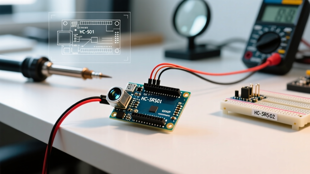
For hobbyists and professionals alike, the HC-SR501 remains the undisputed standard for motion detection sensor Arduino projects. It is inexpensive, operates on standard 5V logic, and features onboard signal conditioning via the BISS0001 micro-power PIR controller IC. However, while basic tutorials simply show you how to read a digital pin, real-world deployments require a deeper understanding of the module's analog adjustments, timing quirks, and power supply sensitivities. This guide provides a comprehensive, expert-level walkthrough for integrating the HC-SR501 with the Arduino Uno R4 platform in 2026.
2026 Component Checklist & Pricing
Before wiring the circuit, ensure you have the following components. Prices reflect average market rates for authentic or high-quality clone components as of early 2026:
- Microcontroller: Arduino Uno R4 WiFi (~$27.50) or Uno R4 Minima (~$17.50). The R4 series offers superior ADC resolution and processing speed over the legacy R3.
- Sensor Module: HC-SR501 PIR Motion Sensor (~$2.50 - $3.50). Ensure it includes the white hemispherical Fresnel lens.
- Power Filtering: 100µF 16V Electrolytic Capacitor (~$0.15). Critical for preventing false triggers on noisy power rails.
- Indicator: 5mm LED and a 220Ω current-limiting resistor.
- Wiring: Female-to-male and male-to-male Dupont jumper wires.
Hardware Anatomy: Potentiometers and Jumpers
The HC-SR501 is not just a simple digital switch; it features onboard analog tuning. Underneath the module, you will find two orange trimpots (potentiometers) and a three-pin jumper header. Understanding these is the difference between a reliable security system and a frustratingly erratic one.
1. Sensitivity Adjustment (Left Potentiometer)
This potentiometer adjusts the detection range. Turning it fully clockwise maximizes the sensitivity, allowing the sensor to detect motion up to 7 meters away with a 120-degree cone angle. Turning it fully counter-clockwise reduces the range to approximately 3 meters. For indoor room applications, setting it to the middle position (roughly 4.5 meters) usually prevents false triggers from adjacent hallways.
2. Time Delay Adjustment (Right Potentiometer)
This controls how long the output pin stays HIGH after motion is no longer detected. The range is logarithmic, spanning from 0.3 seconds (fully counter-clockwise) to roughly 200 seconds (fully clockwise). Expert Tip: When testing, turn this fully counter-clockwise. Waiting 3 minutes for the pin to reset during a debugging session is a common beginner mistake.
3. Retrigger (H) vs. Non-Retrigger (L) Jumper
Located near the potentiometers, this jumper dictates the timing logic of the BISS0001 chip:
- H Mode (Retrigger - Default): The output stays HIGH as long as motion is continuously detected. The timer resets with every new movement. This is ideal for lighting control.
- L Mode (Non-Retrigger): The output goes HIGH for the set delay time, then goes LOW, regardless of ongoing motion. It will ignore all movement during the LOW recovery phase. This is useful for counting distinct entry events.
Wiring the Motion Detection Sensor to Arduino
The HC-SR501 requires a stable 5V power supply. While it can technically operate down to 4.5V, voltage drops below this threshold will cause the internal voltage regulator to fail, resulting in a permanently HIGH or oscillating output pin. According to the Arduino Uno R4 WiFi hardware specifications, the 5V pin can supply sufficient current for the PIR module, provided you are powering the board via the USB-C port or the barrel jack.
| HC-SR501 Pin | Arduino Uno R4 Pin | Function & Notes |
|---|---|---|
| VCC | 5V | Requires stable 5V. Do not use 3.3V. |
| OUT | Digital Pin 2 | Digital HIGH (3.3V) when triggered. |
| GND | GND | Common ground with the microcontroller. |
Non-Blocking Arduino C++ Code
Most beginner tutorials use the delay() function to handle motion timing. This blocks the microcontroller, preventing it from reading other sensors or managing network connections. As detailed in the Adafruit PIR Sensor Guide, professional implementations use state-change detection and non-blocking timers. The code below utilizes millis() to track motion states without halting the main loop.
const int PIR_PIN = 2;
const int LED_PIN = 13;

int pirState = LOW;
int val = 0;
unsigned long lastTriggerTime = 0;
const unsigned long cooldownPeriod = 5000; // 5-second software cooldown

void setup() {
  pinMode(PIR_PIN, INPUT);
  pinMode(LED_PIN, OUTPUT);
  Serial.begin(115200);

  // Allow the sensor to calibrate its IR baseline
  Serial.println("Calibrating sensor... Do not move for 30 seconds.");
  for(int i = 0; i < 30; i++) {
    Serial.print(".");
    delay(1000);
  }
  Serial.println("\nSensor Active.");
}

void loop() {
  val = digitalRead(PIR_PIN);
  unsigned long currentMillis = millis();

  if (val == HIGH) {
    digitalWrite(LED_PIN, HIGH);
    if (pirState == LOW) {
      Serial.println("Motion Detected!");
      pirState = HIGH;
      lastTriggerTime = currentMillis;
    }
  } else {
    // Implement a software cooldown to prevent serial flooding
    if (pirState == HIGH && (currentMillis - lastTriggerTime > cooldownPeriod)) {
      digitalWrite(LED_PIN, LOW);
      Serial.println("Motion Ended.");
      pirState = LOW;
    }
  }

  // The MCU is free to perform other tasks here (e.g., WiFi polling)
}
Advanced Troubleshooting & Edge Cases
When deploying a motion detection sensor Arduino setup in a real-world environment, you will inevitably encounter edge cases that breadboard testing rarely reveals. Here is how to solve the most common hardware-level failures.
Critical Warning: Never place the HC-SR501 directly facing an HVAC vent, radiator, or direct sunlight. The sensor detects changes in infrared energy, not absolute temperature. A blast of warm air from a heater will mimic a human body moving across the Fresnel lens segments, causing immediate false positives.
1. The 60-Second Initialization Blind Spot
The BISS0001 chip requires time to sample the ambient infrared environment and establish a baseline upon receiving power. If you upload your code and immediately test the sensor, it will either fail to trigger or trigger continuously. Always implement a 30 to 60-second blocking delay in your setup() function, or use a non-blocking initialization state machine, to allow the pyroelectric crystal to stabilize.
2. Power Supply Ripple and the Capacitor Fix
If your Arduino is powered via a cheap USB wall adapter or a long, thin USB cable, the 5V rail will contain high-frequency voltage ripple. The HC-SR501's internal op-amps are highly sensitive to power fluctuations and will interpret this ripple as thermal motion, causing the OUT pin to randomly pulse HIGH. The Fix: Solder a 100µF electrolytic capacitor directly across the VCC and GND pins on the back of the PIR module. This acts as a local energy reservoir, smoothing out transient voltage drops and eliminating 90% of phantom triggers.
3. Pet Immunity and Lens Masking
The standard HC-SR501 does not have native pet immunity. If you are building a security system that should ignore cats or dogs, you have two options. First, mount the sensor higher on the wall (at least 2.2 meters up) and tilt it slightly upward so the lower segments of the Fresnel lens do not cover the floor. Second, apply opaque electrical tape over the bottom three rows of the Fresnel lens dome. This physically blocks IR energy from the floor level from reaching the pyroelectric sensor elements.
Summary
Mastering the HC-SR501 motion detection sensor with an Arduino goes far beyond reading a digital pin. By understanding the BISS0001 timing modes, implementing non-blocking C++ state machines, and addressing power supply noise with proper decoupling capacitors, you can transform a $3 hobbyist module into a robust, commercial-grade peripheral. Whether you are building an automated closet light or a multi-node IoT security system, these hardware and software foundations will ensure reliable operation in 2026 and beyond.