
The Reality of Ultrasonic Sensing in 2026
Ultrasonic distance measurement remains a staple in robotics and automation, but integrating a sonar sensor Arduino setup is rarely as plug-and-play as beginners are led to believe. Whether you are using the ubiquitous $2.50 HC-SR04, the IP67-rated JSN-SR04T waterproof transceiver ($9-$12), or a premium MaxBotix LV-MaxSonar module ($30+), acoustic sensors are inherently susceptible to environmental noise, voltage starvation, and timing bottlenecks. When troubleshooting sonar sensor Arduino errors, the root cause is rarely a defective sensor; it is almost always a mismatch between the sensor's analog acoustic reality and the microcontroller's digital expectations.
This guide bypasses generic advice and dives deep into the specific hardware, acoustic, and software failure modes that cause erratic readings, 0 cm returns, and system lockups.
Diagnostic Matrix: Symptom to Solution
Before ripping apart your breadboard, match your specific failure mode to the diagnostic matrix below. This will save you hours of blind troubleshooting.
| Observed Symptom | Probable Root Cause | Actionable Fix |
|---|---|---|
| Constant "0 cm" or "0" return | Echo pulse exceeds timeout or power brownout during ping. | Add 100µF decoupling capacitor; verify ping() timeout limits. |
| Erratic jumping (e.g., 45cm to 12cm to 90cm) | Acoustic cross-talk, soft target absorption, or 3.3V/5V logic mismatch. | Implement median filtering; add voltage divider to Echo pin. |
| Readings freeze or MCU reboots | Blocking pulseIn() function causing watchdog timeout or stack overflow. | Migrate to hardware-timer interrupts via the NewPing library. |
| Accurate at close range, fails past 1.5m | Trigger pulse too short or 5V rail sagging under load. | Extend trigger pulse to 15µs; power sensor from dedicated 5V buck converter. |
Hardware-Level Failures: Voltage Mismatches and Power Starvation
The 3.3V vs 5V Logic Trap
The most common catastrophic failure in modern sonar sensor Arduino projects occurs when pairing 5V sensors (like the HC-SR04) with 3.3V microcontrollers like the ESP32-S3 or Raspberry Pi Pico. The HC-SR04 Echo pin outputs a 5V HIGH signal. Feeding 5V into a 3.3V GPIO pin will either fry the silicon or trigger the MCU's internal clamping diodes, resulting in floating, erratic readings.
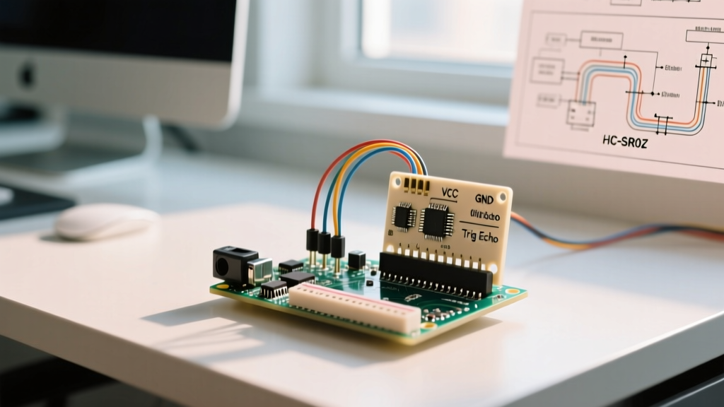
Expert Fix: Never use a simple resistor on the Echo line. You must use a voltage divider. Connect a 1kΩ resistor (R1) in series with the Echo pin, and a 2kΩ resistor (R2) from the junction to ground. This safely steps the 5V echo down to ~3.33V. For high-speed reliability, use a dedicated logic level shifter like the TXS0102. See SparkFun's guide on voltage dividers for exact breadboard layouts.
Power Rail Sag and the "0 cm" Brownout
When the HC-SR04 fires its 40kHz burst, it draws a transient current spike of up to 30mA. If your Arduino Nano or ESP32 is powered via a long, thin USB cable, the voltage rail can momentarily sag below 4.5V. The sensor's internal comparator resets, the Echo pin never goes HIGH, and your code registers a timeout (0 cm).
- The Fix: Solder a 100µF electrolytic capacitor directly across the VCC and GND pins on the sensor's PCB. This acts as a local energy reservoir, absorbing the transient spike without pulling down the main logic rail.
- Trigger Pulse Width: The HC-SR04 datasheet specifies a 10µs trigger pulse. In noisy environments, extend this to 15µs in your code to ensure the internal latch reliably registers the trigger.
Acoustic Anomalies: Blind Zones and Cross-Talk
Waterproof JSN-SR04T Blind Zones
If you are using the waterproof JSN-SR04T for outdoor or liquid-level sensing, you must account for its physical blind zone. Unlike the HC-SR04 (which has a ~2cm blind zone), the JSN-SR04T transceiver mesh requires time to stop ringing after the transmit burst. Version 1.0 has a blind zone of 20cm, while Version 2.0 extends this to 25cm. If your target is inside this zone, the sensor will return erratic garbage data or 0. You must physically mount the sensor at least 30cm away from the maximum possible fill level of your tank.
Multi-Sensor Cross-Talk
Deploying an array of three or more sonar sensors for robotic navigation? If you fire them simultaneously, the Echo pin of Sensor A will pick up the 40kHz bounce from Sensor B. Sound travels at roughly 343 meters per second at 20°C. To completely eliminate cross-talk, you must enforce a sequential firing delay. Calculate the maximum distance (e.g., 4 meters round-trip = 8 meters total travel). 8m / 343m/s = ~23ms. Always enforce a minimum 35ms delay between pings in a multi-sensor array.
Software Bottlenecks: Ditching pulseIn() for Timer Interrupts
The standard Arduino pulseIn() function is a blocking call. According to the official Arduino pulseIn documentation, if no pulse is detected, the function waits for the default timeout of 1,000,000 microseconds (1 full second). In a robotics loop running at 50Hz, a single missed echo will freeze your entire system for a second, causing motors to overshoot and PID loops to fail.
Implementing the NewPing Library
To achieve professional-grade reliability, abandon pulseIn() and use the NewPing library. NewPing utilizes hardware timer interrupts, meaning the MCU can continue executing motor control code while waiting for the echo.
Follow these implementation steps for bulletproof readings:
- Install via Library Manager: Search for "NewPing" by Tim Eckel.
- Set Realistic Maximums: Initialize the sensor with your actual physical maximum distance.
NewPing sonar(12, 13, 200);(Trigger, Echo, Max 200cm). This prevents the library from waiting for echoes that will never return. - Use Median Filtering: Acoustic noise causes occasional outliers. Instead of
sonar.ping_cm(), usesonar.ping_median(5). This fires 5 rapid pings, discards the highest and lowest anomalies, and returns the median value, virtually eliminating erratic jumping.
#include <NewPing.h>
#define TRIGGER_PIN  12
#define ECHO_PIN     13
#define MAX_DISTANCE 200

NewPing sonar(TRIGGER_PIN, ECHO_PIN, MAX_DISTANCE);

void setup() {
  Serial.begin(115200);
}

void loop() {
  // ping_median(5) takes 5 readings and returns the median, filtering acoustic noise
  unsigned int median_distance = sonar.ping_median(5) / US_ROUNDTRIP_CM;
  Serial.print("Distance: ");
  Serial.print(median_distance);
  Serial.println(" cm");
  delay(35); // Mandatory 35ms delay for acoustic settling
}
Environmental Edge Cases: Temperature and Target Density
Finally, true precision requires compensating for the physics of sound. The speed of sound is not a constant 343 m/s; it fluctuates with ambient temperature according to the formula: v = 331.4 + (0.6 × T°C). If your sonar sensor Arduino project operates in an unheated warehouse at 0°C versus a hot factory floor at 40°C, the speed of sound changes by nearly 7%. Over a 3-meter distance, this introduces a 10 cm error. For high-precision industrial applications, wire a DS18B20 temperature sensor alongside your ultrasonic module and apply dynamic compensation in your code.
Furthermore, be aware of target density. 40kHz ultrasonic waves are easily absorbed by soft materials like foam, heavy clothing, or acoustic insulation. If your robot is failing to detect soft obstacles, you must supplement your sonar array with infrared Time-of-Flight (ToF) sensors like the VL53L1X to cover the acoustic blind spots.