
The Evolution of Arduino LCD I2C Interfacing
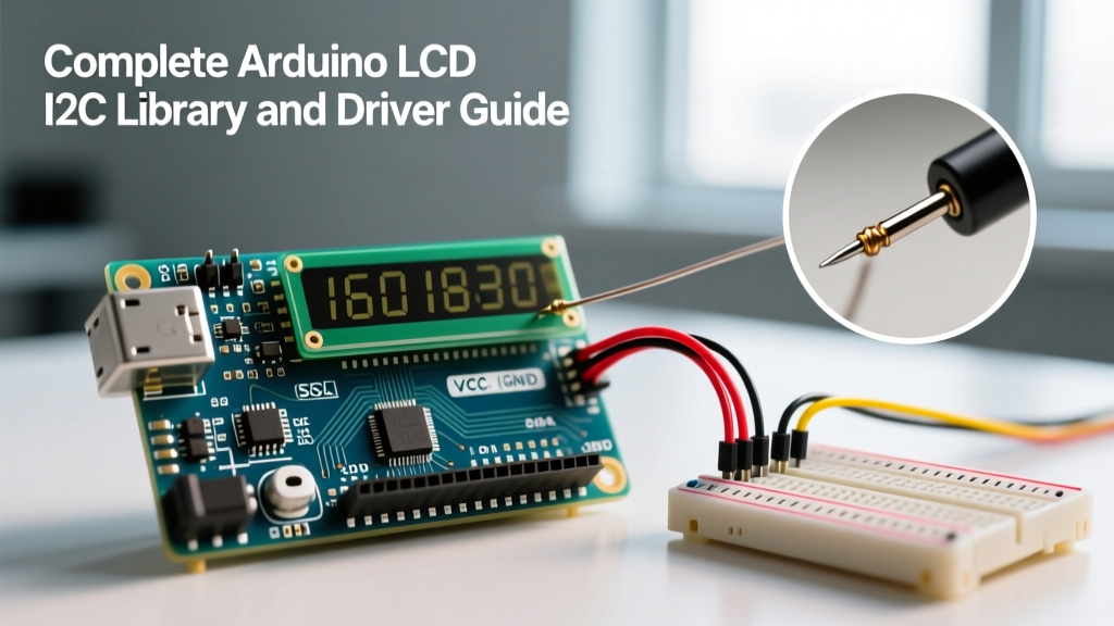
Integrating a character display into a microcontroller project used to require sacrificing six or more digital I/O pins. Today, the arduino lcd i2c configuration is the undisputed standard for hobbyists and prototyping engineers, reducing the wiring footprint to just two pins (SDA and SCL) while maintaining the classic 16x2 or 20x4 form factor. However, as of 2026, the software ecosystem surrounding these displays remains a minefield of outdated tutorials, hardcoded pin mappings, and address conflicts.
This guide cuts through the legacy noise. We will dissect the hardware realities of I2C backpacks, compare the dominant libraries, and provide a definitive framework for diagnosing and driving HD44780-based LCDs without guesswork.
Hardware Reality: Understanding the I2C Backpack
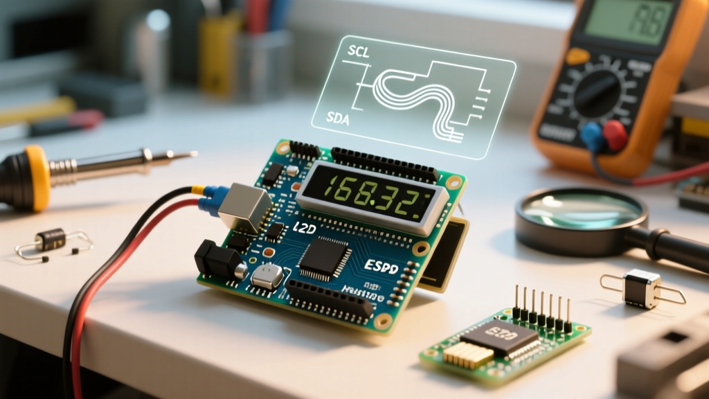
Before writing a single line of code, you must understand the silicon bridging your microcontroller to the LCD. The bare LCD module relies on the Hitachi HD44780U (or modern equivalents like the NHD-0216K1Z) parallel controller. Because I2C is a serial protocol, an intermediary "backpack" board is soldered to the LCD's 16-pin header to perform serial-to-parallel conversion.
There are two primary I2C expander chips used on these backpacks, and confusing them is the root cause of 90% of initialization failures.
| Expander Chip | Manufacturer | I2C Protocol | Common Base Addresses | Market Prevalence |
|---|---|---|---|---|
| PCF8574 (or PCF8574T) | NXP / TI | Simple 8-bit I/O latch | 0x27 (PCF8574T) 0x3F (PCF8574AT) |
~95% of generic market |
| MCP23008 | Microchip | Multi-register configuration | 0x20 - 0x27 | Rare on cheap clones, common on Adafruit |
According to the Texas Instruments PCF8574 datasheet, the chip simply mirrors the I2C data byte directly to its 8 output pins (P0-P7). This simplicity makes it cheap (generic 16x2 LCDs with PCF8574 backpacks retail between $4.50 and $7.00), but it means the physical wiring from the expander pins to the LCD's RS, RW, EN, and D4-D7 pins is entirely up to the manufacturer. There is no universal standard for this trace routing.
The Library Showdown: Why Most Tutorials Fail
If you search the Arduino Library Manager for LCD drivers, you will be bombarded with options. Choosing the wrong one guarantees hours of troubleshooting blank screens.
1. LiquidCrystal_I2C (The Legacy Trap)
Originally authored by Frank de Brabander and later forked by marcoschwartz, this library is the most downloaded but the most problematic. It requires you to manually define the I2C address and the exact pin mapping (e.g., LiquidCrystal_I2C lcd(0x27, 2, 1, 0, 4, 5, 6, 7, 3, POSITIVE);). Because cheap manufacturers constantly change their PCB trace layouts to save fractions of a cent, a hardcoded pin map from a 2018 tutorial will likely fail on a board purchased in 2026.
2. hd44780 (The Gold Standard)
Authored by Bill Perry, the hd44780 library is a masterclass in embedded software design. Instead of forcing the user to guess the pin mapping, the library's hd44780_I2Cexp class automatically scans the I2C bus, identifies the expander chip, and runs a diagnostic routine to deduce the exact pin mapping by toggling pins and reading the LCD's busy flag. As noted in the official Arduino Library Reference, it supports auto-detection for both PCF8574 and MCP23008 architectures seamlessly.
3. Noiasca LiquidCrystal
A highly optimized, modern alternative that focuses on memory efficiency and extended character set support (like Cyrillic or custom ROMs). Excellent for ATtiny85 builds where SRAM is measured in bytes, but slightly less beginner-friendly for diagnostics than hd44780.
Step-by-Step: Auto-Diagnosing Your Display
Stop guessing your I2C address. Follow this exact procedure using the hd44780 library to map your hardware in under three minutes.
- Install the Library: Open the Arduino IDE Library Manager, search for
hd44780by Bill Perry, and install it. - Wire the Hardware: Connect VCC to 5V (not 3.3V, as the LCD logic requires 5V for proper contrast), GND to GND, SDA to A4 (on Uno/Nano) or D2 (on ESP32), and SCL to A5 or D22.
- Run I2CexpDiag: Navigate to File > Examples > hd44780 > ioClass > hd44780_I2Cexp > I2CexpDiag.
- Read the Serial Output: Open the Serial Monitor at 9600 baud. The sketch will output the exact I2C address, the expander chip type, and the deduced pin mapping.
Expert Tip: If I2CexpDiag reports that the I2C bus is "dead" or finds no devices, do not assume the LCD is broken. 99% of the time, this indicates missing pull-up resistors on the SDA/SCL lines or a counterfeit ATmega328P with a non-functional hardware I2C peripheral.
Advanced Troubleshooting & Edge Cases
Even with the correct library, hardware physics and manufacturing defects can cause failures. Here is how to resolve the most persistent edge cases.
The Contrast Potentiometer Blindness
A completely blank LCD with a lit backlight usually means the contrast voltage (V0) is out of range. On the back of the PCF8574 backpack, there is a blue 10K trimpot. The HD44780 controller requires the V0 pin to be approximately 0.4V to 0.6V relative to ground to render pixels. If the trimpot is at its maximum resistance, V0 floats near 5V, rendering the liquid crystals completely transparent. Use a multimeter to probe the V0 pin while turning the trimpot until you hit ~0.5V.
I2C Bus Capacitance on Long Runs
The I2C specification limits bus capacitance to 400pF. In practical terms, using standard jumper wires longer than 30cm between the Arduino and the LCD backpack will degrade the signal edges, causing the PCF8574 to miss ACK bits.
- Solution 1: Solder 4.7kΩ pull-up resistors between SDA/SCL and 5V directly at the LCD backpack.
- Solution 2: For runs exceeding 50cm, drop the pull-up value to 2.2kΩ or use an active I2C bus extender like the P82B96.
Address Collisions: 0x27 vs 0x3F
Many tutorials hardcode 0x27 as the I2C address. However, manufacturers frequently use the PCF8574AT chip instead of the PCF8574T. The 'A' variant shifts the base address to 0x3F. If you are building a device with multiple sensors on the same bus, relying on hardcoded addresses will lead to collisions. Always use the auto-detection features of the hd44780_I2Cexp class, which pings all 8 possible PCF8574 addresses (0x20-0x27 and 0x38-0x3F) during the lcd.begin() initialization sequence.
Production-Ready Code Implementation
Below is the minimal, robust implementation for initializing an Arduino LCD I2C setup using the auto-detection methodology. This code avoids hardcoded addresses and ensures the display clears and resets properly upon boot.
#include <Wire.h>
#include <hd44780.h>
#include <hd44780ioClass/hd44780_I2Cexp.h>

// Initialize library without hardcoding address or pinmap
hd44780_I2Cexp lcd;

void setup() {
  Serial.begin(115200);

  // Auto-detects address, pin mapping, and initializes 16x2 display
  int status = lcd.begin(16, 2);

  if (status) {
    Serial.print("LCD init failed: ");
    Serial.println(status);
    // Handle fatal error (e.g., halt or blink onboard LED)
    while(1);
  }

  lcd.print("ElectricalFlux");
  lcd.setCursor(0, 1);
  lcd.print("I2C Ready 2026");
}

void loop() {
  // Main application logic
}
Summary
The transition from parallel to I2C LCDs saved valuable microcontroller pins, but introduced a layer of abstraction that trips up even experienced makers. By abandoning legacy libraries like LiquidCrystal_I2C in favor of the auto-diagnosing hd44780 library, and by respecting the electrical realities of the PCF8574 expander and I2C bus capacitance, you can achieve 100% reliable display integration in your 2026 embedded projects.