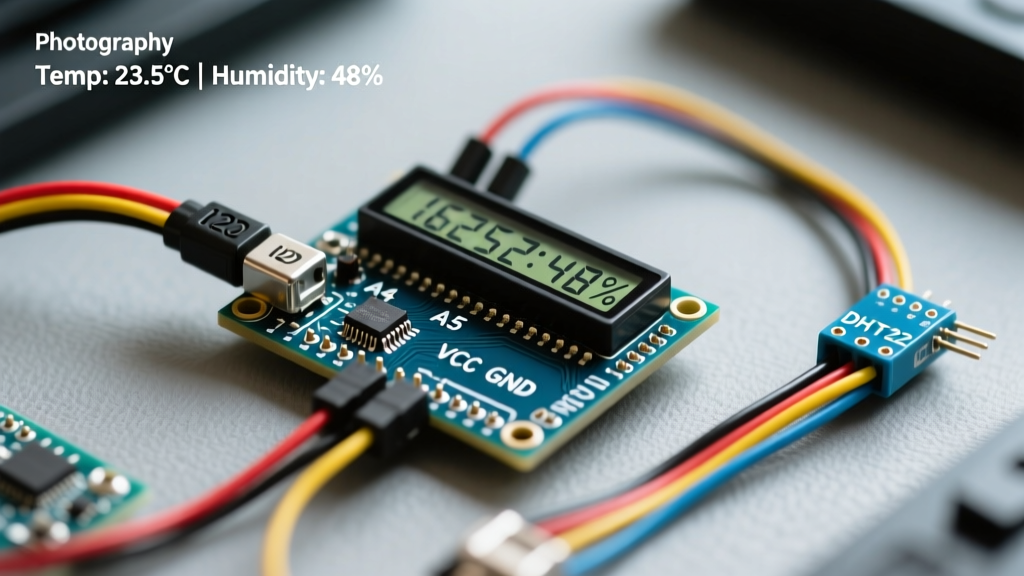

Why Choose I2C for Your Arduino Display LCD Setup?
When integrating environmental or proximity sensors with a microcontroller, displaying real-time telemetry is crucial for field debugging and standalone operation. Historically, wiring a standard 16x2 or 20x4 parallel character LCD required six digital I/O pins, leaving fewer resources for your actual sensors. In 2026, the industry standard for hobbyist and prototyping sensor integration is the I2C serial interface. By utilizing a PCF8574 I/O expander backpack, an Arduino display LCD setup requires only two analog pins (SDA and SCL), freeing up critical GPIOs for DHT22 temperature sensors, HC-SR04 ultrasonic modules, or PIR motion detectors.
| Feature | Parallel (4-bit Mode) | I2C (PCF8574 Backpack) |
|---|---|---|
| Pins Required | 6 (RS, EN, D4-D7) | 2 (SDA, SCL) |
| Wiring Complexity | High (prone to breadboard errors) | Low (standardized 4-pin header) |
| Library Dependency | LiquidCrystal.h | LiquidCrystal_I2C.h |
| Sensor Headroom | Limited on ATmega328P | Maximum GPIO availability |
According to the official Arduino I2C communication documentation, the I2C bus supports up to 128 devices, meaning you can easily daisy-chain multiple sensor modules alongside your LCD on the same SDA/SCL lines without pin contention.
Hardware Requirements and 2026 Pricing
For a robust sensor integration project, you need reliable hardware. While generic modules are cheap, they often suffer from poor solder joints on the contrast potentiometer. Here is a breakdown of current market options:
- Generic 1602 I2C LCD (PCF8574T): $3.50 – $5.00. Best for budget prototypes, but requires manual contrast calibration.
- DFRobot Gravity I2C 16x2 LCD: $8.99. Features a standardized Gravity connector, eliminating breadboard jumper wire failures.
- Adafruit RGB Positive 16x2 LCD: $24.95. Includes an onboard RGB backlight controller and an integrated I2C expander. Highly recommended for professional enclosures where status-color coding (e.g., Red for high temp, Green for normal) is required.
The I2C Address Conflict Problem
A common failure point when integrating an Arduino display LCD with other I2C sensors (like the BME280 or MPU6050) is an address collision. Most inexpensive I2C backpacks use the NXP PCF8574T chip, which defaults to the hex address 0x27. However, some manufacturers use the PCF8574AT chip, which defaults to 0x3F. If your LCD fails to initialize while other sensors work, you are likely using the wrong address. You can verify your specific module's address by running the standard I2C Scanner sketch from the Arduino IDE examples menu before writing your main integration code.
Step-by-Step Wiring: DHT22 Sensor to I2C LCD
For this tutorial, we are integrating a DHT22 (AM2302) temperature and humidity sensor. The DHT22 requires a 4.7kΩ pull-up resistor on its data line for stable readings over longer wire runs. Below is the exact pinout for an Arduino Uno R3 or R4 Minima.
| Component | Pin | Arduino Uno Connection | Notes |
|---|---|---|---|
| I2C LCD | GND | GND | Common ground required |
| I2C LCD | VCC | 5V | Requires 5V for backlight |
| I2C LCD | SDA | A4 (Uno R3) / SDA (R4) | I2C Data Line |
| I2C LCD | SCL | A5 (Uno R3) / SCL (R4) | I2C Clock Line |
| DHT22 | VCC | 5V | 3.3V works but 5V is safer |
| DHT22 | DATA | Digital Pin 2 | 4.7kΩ pull-up to 5V |
| DHT22 | GND | GND | Common ground |
Writing the C++ Integration Code
When displaying live sensor data, beginners often use lcd.clear() inside the main loop(). This causes a severe, visible flicker because the display blanks out before redrawing the characters. The professional approach is to overwrite the specific character coordinates only when the data changes, or pad your strings with spaces to overwrite old digits without clearing the screen.
Furthermore, the DHT22 has a hardware-mandated 2-second sampling limit. Using delay(2000) blocks the microcontroller, preventing you from reading other sensors or handling button inputs. We use a non-blocking millis() timer instead.
#include <Wire.h>
#include <LiquidCrystal_I2C.h>
#include <DHT.h>

// Initialize I2C LCD (Address 0x27, 16 columns, 2 rows)
LiquidCrystal_I2C lcd(0x27, 16, 2);

#define DHTPIN 2
#define DHTTYPE DHT22
DHT dht(DHTPIN, DHTTYPE);

unsigned long lastReadTime = 0;
const long readInterval = 2500; // DHT22 needs 2s minimum

void setup() {
  lcd.init();
  lcd.backlight();
  dht.begin();

  // Static labels drawn once to prevent flicker
  lcd.setCursor(0, 0);
  lcd.print("Temp:");
  lcd.setCursor(0, 1);
  lcd.print("Hum:");
}

void loop() {
  unsigned long currentMillis = millis();

  if (currentMillis - lastReadTime >= readInterval) {
    lastReadTime = currentMillis;

    float t = dht.readTemperature();
    float h = dht.readHumidity();

    // Check if reads failed (NaN)
    if (isnan(t) || isnan(h)) {
      lcd.setCursor(5, 0);
      lcd.print("Sensor Err  ");
      return;
    }

    // Overwrite values with space-padding to clear old digits
    lcd.setCursor(5, 0);
    lcd.print(t, 1); // 1 decimal place
    lcd.print((char)223); // Degree symbol
    lcd.print("C   ");    // Padding spaces

    lcd.setCursor(4, 1);
    lcd.print(h, 1);
    lcd.print("%   ");
  }
}
Contrast Calibration and Ghosting Artifacts
Upon first powering up your Arduino display LCD, you may see the backlight illuminate but no text. This is rarely a code error; it is a V0 contrast voltage issue. On the back of the PCF8574 backpack is a small blue trimmer potentiometer. Using a small Phillips head screwdriver, turn this pot slowly while the Arduino is powered. As the Adafruit Character LCD Guide notes, the V0 pin controls the voltage differential between the LCD glass and the liquid crystals. Too high, and the screen is blank; too low, and you get 'ghosting' (solid black blocks on every character grid).
Real-World Failure Modes and Edge Cases
Even with perfect code, hardware integration in the field presents unique challenges. Here is a troubleshooting matrix based on common field failures:
| Symptom | Probable Cause | Engineering Fix |
|---|---|---|
| Solid white boxes on top row | Contrast pot misconfigured or 5V sag | Adjust blue trimmer; check USB power supply amperage. |
| Backlight on, completely blank | I2C address mismatch (0x3F vs 0x27) | Run I2C Scanner sketch and update LiquidCrystal_I2C constructor. |
| Text prints but shifts randomly | Missing pull-up resistors on SDA/SCL | Add 4.7kΩ pull-ups to 5V on both I2C lines. |
| Flickering display during sensor read | Using lcd.clear() in loop |
Use space-padding overwrite method as shown in code above. |
| NaN Sensor Readings | DHT22 polling too fast or missing pull-up | Enforce >2000ms delay; verify 4.7kΩ resistor on DATA pin. |
Expert Tip: If you are routing I2C cables longer than 30cm (12 inches) to mount your LCD on an enclosure door, the parasitic capacitance of the wires will degrade the square wave clock signal. To fix this, lower the I2C clock speed in your setup function by adding
Wire.setClock(10000);to drop the bus speed from the default 100kHz to 10kHz, ensuring stable data transmission over longer distances.
Frequently Asked Questions
Can I power a 16x2 I2C LCD directly from the Arduino's 3.3V pin?
No. While the logic level of the PCF8574 chip might trigger at 3.3V, the LCD backlight requires a forward voltage of approximately 4.2V to 5.0V. Connecting VCC to 3.3V will result in a dim or completely dead backlight. Always use the 5V pin, and ensure your power supply can handle the ~20mA draw of the LEDs.
How do I display custom icons like a thermometer or battery?
The HD44780 controller inside the LCD supports up to 8 custom 5x8 pixel characters stored in the CGRAM. You can define byte arrays representing your custom sensor icons and write them to memory using the lcd.createChar() function before your main loop begins. The NXP PCF8574 datasheet outlines how the I2C expander translates these serial commands into the parallel signals required by the HD44780 controller.
Is an OLED display better than an LCD for sensor data?
OLEDs (SSD1306) offer higher contrast and do not require backlights, making them superior for dark environments. However, I2C character LCDs are significantly cheaper, easier to read in direct sunlight, and require vastly less RAM (a 16x2 LCD requires only a few bytes of buffer, whereas a 128x64 OLED requires a 1KB framebuffer, which can starve the SRAM on an ATmega328P when running complex sensor fusion algorithms).