
The Global "Sensor Infravermelho Arduino" Phenomenon
Whether you are sourcing components from local Brazilian electronics markets or ordering in bulk from global suppliers, the search term "sensor infravermelho arduino" represents one of the most common entry points into MCU peripherals. Infrared (IR) receivers are cheap, ubiquitous, and deceptively complex. In 2026, while the Arduino ecosystem has matured with libraries like IRremote v4.4+, hardware-level failures remain the primary culprit behind ghost signals, dropped packets, and abysmal range.
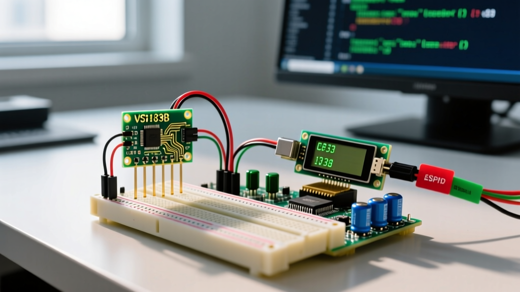
This guide bypasses basic tutorials and dives straight into the electrical engineering realities of IR photodiodes, Automatic Gain Control (AGC) saturation, and power rail noise. We will troubleshoot the most common IR receiver ICs, including the generic VS1838B and the industry-standard Vishay TSOP38238.
Component Anatomy: VS1838B vs. TSOP38238
Not all 38kHz IR receivers are created equal. Understanding the silicon inside your plastic dome is the first step in troubleshooting.
| Specification | Generic VS1838B | Vishay TSOP38238 |
|---|---|---|
| Average Cost (2026) | $0.08 - $0.12 | $1.10 - $1.35 |
| AGC Algorithm | Basic (prone to CFL noise) | Advanced (suppresses optical noise) |
| Supply Current | ~1.5mA | ~0.35mA (ultra-low power) |
| Data Sheet Reliability | Non-existent / Cloned | Strict Vishay specifications |
If your project is deployed in a living room with modern LED/CFL lighting, the VS1838B will likely suffer from continuous noise. The Vishay TSOP382xx Datasheet explicitly details how their AGC filters out continuous 38kHz noise from fluorescent ballasts, a feature often missing in budget clones.
Hardware Failure Mode 1: The "Ghost Signal" Plague
Symptom
Your Arduino serial monitor prints random IR codes or continuously triggers the IrReceiver.decode() function even when no remote is pressed.
The Root Cause: Power Rail Ripple & Optical Noise
IR receivers contain a high-gain preamplifier. When the Arduino's 5V rail experiences voltage ripple (common when sharing power with servos, Wi-Fi modules like the ESP32, or multiplexed displays), this ripple couples into the receiver's VCC pin. Furthermore, the internal AGC ramps up sensitivity during quiet periods, making the IC hyper-sensitive to ambient optical noise.
The Expert Fix
- Decoupling Capacitor: Solder a 10µF to 100µF electrolytic capacitor directly across the VCC and GND pins of the IR receiver.
- Series Isolation Resistor: Add a 10Ω to 100Ω resistor in series with the VCC line before the capacitor. This creates an RC low-pass filter that starves high-frequency MCU noise from reaching the sensor.
Pro Tip: Never wire an IR receiver directly to the same 5V bus as a sweeping servo motor. The servo's back-EMF will cause brownouts in the IR preamplifier, resulting in corrupted NEC or RC5 protocol frames.
Hardware Failure Mode 2: Environmental Interference & EMI
Modern 2026 households are filled with switch-mode power supplies (SMPS) and high-frequency LED drivers. These devices often leak electromagnetic interference (EMI) and optical noise in the 30kHz to 50kHz range. If your sensor infravermelho arduino setup works perfectly on a workbench but fails when installed near a smart TV or dimmable LED ceiling lights, you are experiencing AGC saturation. The receiver's internal gain maxes out trying to pierce the ambient noise floor, rendering it deaf to your actual remote control. Moving the receiver away from SMPS transformers and adding a physical darkened optical hood (even heat-shrink tubing extended past the dome) drastically reduces this optical saturation.
Hardware Failure Mode 3: KY-022 Pinout Roulette
Symptom
The receiver gets hot, or the Arduino pin reads a permanent HIGH/LOW regardless of IR light.
The Root Cause
The ubiquitous KY-022 breakout module is manufactured by dozens of different factories. While the standard pinout is S (Signal), Middle (VCC), Right (GND), many batches swap the VCC and GND pins. Applying 5V to the ground pin of the internal VS1838B instantly destroys the silicon junction.
The Expert Fix
Always trace the PCB copper. The ground pin will almost always have a thick trace connecting to the large ground pour on the back of the PCB, or it will route directly to the metal shielding can of the IR receiver. Verify with a multimeter's continuity mode against the USB shield ground before applying power.
Hardware Failure Mode 4: Abysmal Range (< 1 Meter)
Symptom
The setup only responds when the remote is pressed within inches of the receiver dome.
The Root Cause: Transmitter Starvation
Troubleshooting isn't just about the receiver; it is often about the transmitter. A standard Arduino GPIO pin can safely source only ~20mA. An IR LED (like the 940nm TSAL6200) requires 100mA to 200mA pulsed current to achieve a 10+ meter range. Driving it directly from a digital pin results in a weak optical output that the receiver's band-pass filter rejects as noise.
The Expert Fix: NPN Transistor Driver
Build a simple pulse driver using a 2N2222 NPN transistor:
- Connect the Arduino PWM pin (e.g., Pin 3) through a 1kΩ base resistor to the base of the 2N2222.
- Connect the emitter to GND.
- Connect the IR LED anode to 5V (or a separate 5V rail).
- Connect the IR LED cathode through a 10Ω current-limiting resistor to the collector of the transistor.
This circuit allows the Arduino to switch 150mA+ pulses through the LED, instantly multiplying your effective range by 5x to 10x.
Software Debugging: Bypassing Protocol Decoders
When hardware checks out but the Arduino refuses to decode the signal, the issue is usually a protocol mismatch. In 2026, the Arduino-IRremote GitHub Repository is the definitive standard. However, relying solely on decode() is a mistake when dealing with obscure AC units or proprietary fans.
Using Raw Dump for Signal Visualization
Instead of guessing the protocol, use the IRrecvDumpV3 example sketch. This outputs the raw microsecond timings of the mark/space intervals.
// Excerpt from IRrecvDumpV3 setup
IrReceiver.begin(RECV_PIN, ENABLE_LED_FEEDBACK);
If you see a repeating pattern of +8950 -4450 followed by 32 bits of data, you are looking at the NEC Protocol. If the header is +2400 -600, you are likely dealing with Sony SIRC. By analyzing raw timings, you can manually reconstruct the hex payload even if the library's decoder fails to recognize a slight timing drift caused by a cheap remote's ceramic resonator.
Frequently Asked Questions (FAQ)
Can sunlight blind the sensor infravermelho arduino?
Yes. Direct sunlight contains massive amounts of broadband infrared radiation. While the 38kHz band-pass filter blocks DC sunlight, the sheer intensity can saturate the internal photodiode, effectively blinding the AGC. Use a darkened optical filter or mount the receiver inside a deep hood/shroud.
Why does my IR receiver output a continuous stream of 0xFFFFFFFF?
This is the NEC protocol's Repeat Frame. When you hold a button down on a standard TV remote, it sends the full data frame once, followed by a special repeat code every 108ms. The IRremote library translates this to 0xFFFFFFFF to indicate a sustained button press without duplicating the original payload.
Is it safe to power the IR receiver from the Arduino 3.3V pin?
Most modern receivers (like the TSOP38238) operate flawlessly from 2.5V to 5.5V. However, the VS1838B clones often require a minimum of 4.5V to maintain their internal oscillator accuracy. If using a 3.3V MCU (like an ESP32 or Arduino Due), stick to the Vishay TSOP series or use a logic level shifter for the data line while powering the receiver from a 5V source. For more on optical sensors, the Adafruit IR Sensor Guide provides excellent foundational wiring diagrams.
Final Verdict
Troubleshooting the sensor infravermelho arduino ecosystem requires looking past the code and into the physics of light and power delivery. By implementing proper RC decoupling, utilizing NPN transistor drivers for your transmitters, and leveraging raw timing dumps in the IRremote library, you can transform a glitchy, unreliable setup into an industrial-grade peripheral interface.