
The Flaw with Resistive Sensors (And Why We Use Capacitive)
If you have ever attempted to build an automated irrigation system using the standard, nickel-plated resistive soil moisture probes, you likely encountered a frustrating failure mode: galvanic corrosion. Resistive sensors pass a direct electrical current through the soil between two exposed electrodes. Over a period of 72 to 96 hours, the electrolysis process rapidly degrades the metal, leaving you with a useless, oxidized piece of fiberglass. In 2026, the industry standard for DIY and prosumer microcontroller integration has definitively shifted to capacitive sensing.
Capacitive soil moisture sensors, such as the widely available v1.2 and v2.0 modules, do not measure electrical resistance. Instead, they measure the dielectric permittivity of the surrounding medium. Water has a dielectric constant of approximately 80, while dry soil sits between 3 and 5, and air is roughly 1. The sensor utilizes an onboard 555 timer IC configured as an astable multivibrator. The soil acts as the dielectric material for the capacitor formed by the sensor's copper traces. As soil moisture increases, the capacitance increases, which in turn lowers the oscillation frequency. An internal low-pass filter converts this frequency into a smooth analog voltage output, providing a highly stable, corrosion-resistant reading.
Bill of Materials (BOM) & Specifications
Before wiring the circuit, ensure you have the correct components. Prices reflect the average Q1 2026 market rates from major electronics distributors.
| Component | Model / Specification | Approx. Price | Engineering Notes |
|---|---|---|---|
| Microcontroller | Arduino Uno R4 Minima | $27.50 | Features a 14-bit ADC, offering vastly superior resolution over the legacy R3's 10-bit ADC. |
| Moisture Sensor | Capacitive Soil Moisture Sensor v1.2 | $3.15 | Ensure the board has the 555 timer IC. Avoid unmarked clones lacking the voltage regulator. |
| Water Pump | 12V DC Diaphragm Pump (60 PSI) | $18.00 | Requires a logic-level MOSFET or relay module; do not drive directly from MCU pins. |
| Conformal Coating | MG Chemicals 419D (Acrylic) | $22.00 | Critical for waterproofing the upper PCB section while leaving the sensing pads exposed. |
Hardware Wiring & Voltage Logic Constraints
The most common point of failure in Arduino analogRead() implementations for soil moisture is ignoring ADC voltage tolerances. The v1.2 capacitive sensor features an onboard 3.3V voltage regulator, but its analog output pin can still swing up to the supplied VCC level.
Scenario A: Wiring to a 5V Arduino (Uno R3/R4, Mega)
If you power the sensor's VCC pin with 5V, the analog output will range from roughly 4.2V (dry) to 2.1V (wet). This is perfectly safe for the ATmega328P or Renesas RA4M1 5V-tolerant ADC pins. Wire the AOUT pin directly to Analog Pin A0.
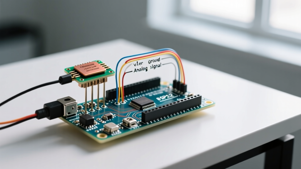
Scenario B: Wiring to a 3.3V MCU (ESP32, Arduino Nano 33 IoT)
If you power the sensor with 5V but connect the AOUT pin to an ESP32 GPIO (which has a strict 3.3V maximum), you will permanently damage the ESP32's ADC channel. Solution: Power the sensor's VCC pin with 3.3V. The analog output will now safely range from ~2.8V (dry) to ~1.4V (wet), keeping it well within the ESP32's safe operating area.
Step-by-Step Calibration Protocol
Capacitive sensors do not output absolute volumetric water content (VWC) percentages out of the box. According to University of Nebraska-Lincoln CropWatch guidelines, accurate VWC requires substrate-specific calibration curves. For a DIY automated watering system, mapping the raw ADC values to a 0-100% relative moisture scale is sufficient.
Upload the following raw data-logging sketch to your Arduino. Open the Serial Monitor at 9600 baud.
void setup() {
  Serial.begin(9600);
}

void loop() {
  int rawValue = analogRead(A0);
  Serial.print("Raw ADC Value: ");
  Serial.println(rawValue);
  delay(1000);
}- Dry Baseline: Hold the sensor in the air, completely dry and clean. Record the average stable value (e.g., 585 on a 10-bit ADC).
- Wet Baseline: Submerge the sensor in a glass of water up to the white silkscreen line (do not submerge the electronic components). Record the lowest stable value (e.g., 290 on a 10-bit ADC).
Production-Ready Code with Hysteresis Logic
A major edge case in automated irrigation is 'relay chatter'—when the moisture level hovers exactly at the threshold, causing the water pump to rapidly cycle on and off, destroying the pump motor and relay contacts. We solve this by implementing hysteresis (a deadband) in the software logic.
const int SENSOR_PIN = A0;
const int PUMP_RELAY_PIN = 8;

// Calibration values from your specific sensor
const int DRY_VALUE = 585;
const int WET_VALUE = 290;

// Hysteresis thresholds (Percentage 0-100)
const int LOW_MOISTURE_THRESH = 30;  // Turn pump ON below this
const int HIGH_MOISTURE_THRESH = 45; // Turn pump OFF above this

bool pumpState = false;

void setup() {
  pinMode(PUMP_RELAY_PIN, OUTPUT);
  digitalWrite(PUMP_RELAY_PIN, LOW); // Ensure pump is off at boot
  Serial.begin(9600);
}

void loop() {
  int rawValue = analogRead(SENSOR_PIN);
  // Constrain and map raw ADC to 0-100 percentage
  int moisturePercent = map(rawValue, DRY_VALUE, WET_VALUE, 0, 100);
  moisturePercent = constrain(moisturePercent, 0, 100);

  // Hysteresis Logic
  if (moisturePercent < LOW_MOISTURE_THRESH && !pumpState) {
    pumpState = true;
    digitalWrite(PUMP_RELAY_PIN, HIGH);
    Serial.println("Pump ON: Soil too dry.");
  }
  else if (moisturePercent > HIGH_MOISTURE_THRESH && pumpState) {
    pumpState = false;
    digitalWrite(PUMP_RELAY_PIN, LOW);
    Serial.println("Pump OFF: Soil sufficiently moist.");
  }

  Serial.print("Moisture: ");
  Serial.print(moisturePercent);
  Serial.println("%");

  delay(2000); // Poll every 2 seconds to allow water to permeate soil
}
Real-World Edge Cases: Waterproofing & Signal Noise
Even though the sensing mechanism is capacitive and immune to galvanic corrosion, the exposed copper traces and the top-mounted 555 timer IC are highly vulnerable to moisture ingress, which will cause short circuits and erratic analog readings.
Proper Conformal Coating Application
As detailed in DigiKey's technical guide on PCB protection, applying a conformal coating is mandatory for outdoor or subterranean electronics. Use an acrylic conformal coating like MG Chemicals 419D.
- Clean the PCB with 99% Isopropyl Alcohol (IPA) to remove manufacturing flux residues.
- Use Kapton tape to mask the bottom 1.5 inches of the sensor (the sensing pads that must make direct contact with the soil dielectric).
- Apply two thin coats of the acrylic spray to the upper section, covering the 555 timer, resistors, and solder joints. Allow 2 hours of cure time between coats.
Mitigating EMI on Long Cable Runs
The analog voltage output from the sensor is high-impedance. If you run standard jumper wires longer than 1.5 meters to your Arduino, the cable will act as an antenna, picking up 50/60Hz electromagnetic interference (EMI) from nearby AC mains wiring. This manifests as wild fluctuations in your analogRead() data.
Engineering Fix: Use a shielded twisted-pair (STP) cable for runs exceeding 1 meter. Connect the shield drain wire to the Arduino's GND pin at the microcontroller end only (to prevent ground loops). Alternatively, place a 0.1µF ceramic capacitor directly between the AOUT pin and GND at the Arduino input to form a hardware low-pass filter, effectively smoothing out high-frequency EMI noise.
Frequently Asked Questions
Why is my capacitive sensor reading completely flat at 1023?
This usually indicates a broken trace or a failed onboard voltage regulator. If you are powering the v1.2 module with 3.3V but the internal LDO requires a minimum dropout voltage, it may fail to oscillate. Always verify the module's silkscreen for voltage requirements; some cheaper clones omit the LDO entirely and require exactly 5V VCC to operate the 555 timer correctly.
Can I use this sensor to measure the water level in a tank?
While technically possible, capacitive soil sensors are optimized for the dielectric profile of soil matrices. For liquid tank level sensing, a dedicated non-contact capacitive liquid level module (like the XKC-Y25) or a standard hydrostatic pressure transducer is vastly superior and more linear.
How often should I recalibrate the sensor?
Capacitive sensors are remarkably stable over time. However, if you change the soil composition (e.g., moving from dense clay to a highly aerated perlite/peat mix), the baseline dielectric properties of the 'dry' and 'wet' states will shift. Recalibrate the DRY_VALUE and WET_VALUE variables whenever you change the physical substrate.