
Why Datasheets Matter for Your DC Motor and Arduino Setup
Connecting a DC motor and Arduino microcontroller directly is a rite of passage that usually ends in a fried ATmega328P chip. Arduino GPIO pins can source a maximum of 40mA (absolute maximum) at 5V, while even small hobby motors demand amps. To bridge this gap safely, you need a motor driver. But how do you choose the right one, and how do you ensure your power supply won't brown out your microcontroller? The answers lie entirely in the component datasheets.
In this guide, we dissect the datasheets of a highly reliable, industry-standard pairing for 2026 robotics projects: the Pololu 12V 100:1 Metal Gearmotor (Item #4753) (retailing around $21.95) and the Texas Instruments DRV8871 motor driver IC (available on carrier boards for ~$3.50). By understanding the exact specifications, you can eliminate acoustic whine, prevent thermal shutdowns, and design a bulletproof peripheral interface.
Decoding the Motor Datasheet: Pololu 12V 30D Metal Gearmotor
Before writing a single line of PWM code, you must understand the mechanical and electrical limits of your actuator. The Pololu 30D series is a brushed DC motor paired with a planetary gearbox. Here are the critical parameters extracted directly from the manufacturer's specification sheet.
| Datasheet Parameter | Value (12V, 100:1 HP) | Arduino Integration Impact |
|---|---|---|
| No-Load Speed | 130 RPM | Dictates your maximum encoder polling rate. |
| Stall Current | 1.25 A | Your power supply and driver must handle this peak without dropping voltage to the Arduino. |
| Stall Torque | 9 kg·cm (125 oz·in) | Maximum mechanical load before the motor stops and draws peak current. |
| Gearbox Ratio | 100:1 Metal | High reduction multiplies torque but introduces backlash (approx. 1.5 degrees). |
The Torque-Speed Curve and Power Supply Sizing
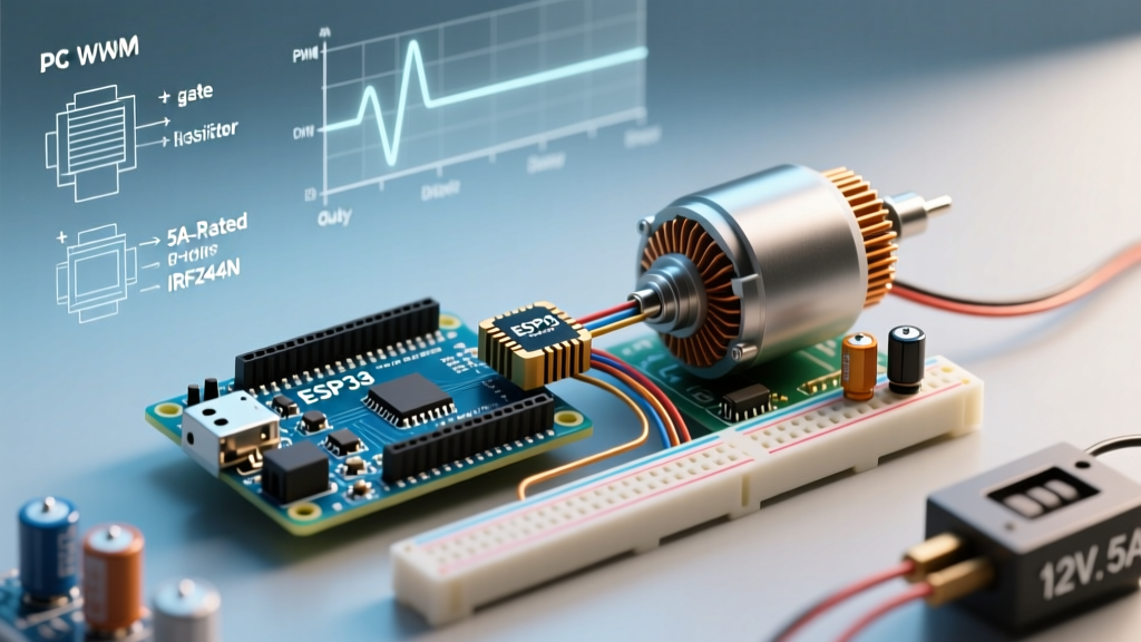
The most misunderstood graph in any motor datasheet is the Torque-Speed curve. It shows a linear inverse relationship: as mechanical load (torque) increases, speed decreases, and current draw spikes. If your robot hits a wall, the motor stalls. At 12V, a stall draws 1.25A. If you attempt to power this motor from the Arduino Uno R3's onboard 5V regulator, the NCP1117 voltage regulator will instantly hit its 800mA thermal limit and shut down, resetting your Arduino Uno. Always use a dedicated external BEC or buck converter rated for at least 3A to power the motor driver's logic and VM pins.
The Driver Datasheet: Texas Instruments DRV8871
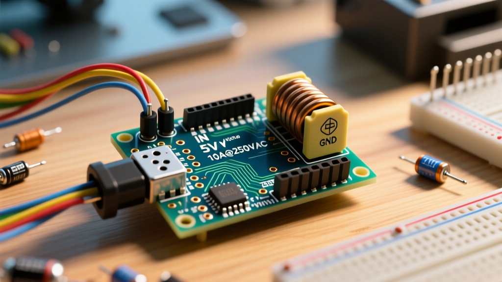
The DRV8871 is an H-bridge motor driver designed specifically to solve the logic-level translation and high-current switching problems inherent in a DC motor and Arduino setup. Let's break down the critical sections of the TI DRV8871 Datasheet.
Logic Thresholds: Will 5V Arduino Logic Work?
Many modern motor drivers require 3.3V logic, which can cause compatibility headaches with 5V Arduinos. The DRV8871 datasheet specifies the logic input thresholds ($V_{IL}$ and $V_{IH}$) based on the VM (motor supply) voltage.
- $V_{IL}$ (Low-Level Input Voltage): Maximum 0.8V (Guaranteed LOW).
- $V_{IH}$ (High-Level Input Voltage): Minimum 2.2V (Guaranteed HIGH).
Expert Insight: Because the Arduino Uno outputs a solid 5V on its digital pins, it easily exceeds the 2.2V $V_{IH}$ threshold. You do not need a logic level shifter for this specific DC motor and Arduino combination, saving you board space and BOM costs.
Current Ratings and Thermal Headroom
The datasheet lists the continuous output current ($I_O$) at 3.6A (with proper PCB copper pour for heatsinking). Since our Pololu motor has a stall current of 1.25A, the DRV8871 provides nearly a 3x safety margin. This prevents the IC's Overcurrent Protection (OCP) from triggering during hard startups or direction reversals, which momentarily spike current draw.
Wiring the DC Motor and Arduino: Step-by-Step
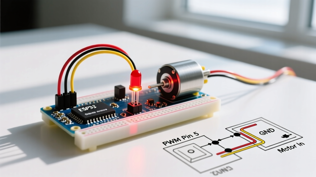
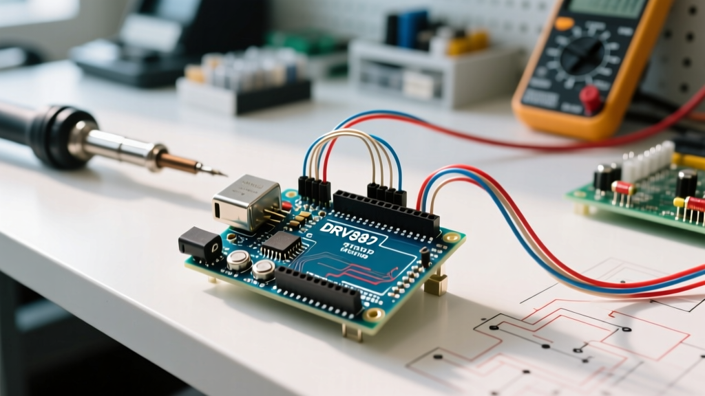
Translating datasheet pinouts into physical wiring requires attention to ground loops and decoupling. Follow this exact schematic layout:
- Power Supply: Connect a 12V 3A DC barrel jack adapter to the breadboard power rails.
- Driver VM Pin: Wire the 12V positive rail to the DRV8871
VMpin. - Common Ground: Connect the 12V supply GND, the DRV8871
GNDpin, and the ArduinoGNDpin together. Never skip the common ground; floating grounds will cause erratic PWM behavior. - Logic Inputs: Connect Arduino Digital Pin 9 (PWM) to DRV8871
IN1, and Digital Pin 10 toIN2. - Motor Terminals: Connect the Pololu motor leads to
OUT1andOUT2. - Decoupling Capacitor: Solder a 100µF electrolytic capacitor directly across the VM and GND pins on the driver board to absorb voltage dips during motor commutation.
Advanced Edge Cases: PWM Whine and Back-EMF
Datasheet Note: The DRV8871 supports PWM frequencies up to 100 kHz. However, the default Arduino analogWrite() function operates at roughly 490 Hz (or 980 Hz on pins 5 and 6).
Solving Acoustic Noise
Running a DC motor at 490 Hz often results in a highly audible, annoying whine. This is because the PWM frequency falls squarely within the human hearing range and causes the motor windings to physically vibrate. To fix this, reconfigure the Arduino's Timer1 to output a 20 kHz PWM signal. At 20 kHz, the frequency is ultrasonic, resulting in silent motor operation. You can achieve this by modifying the TCCR1B register in your setup function:
// Set Timer1 to Phase Correct PWM, 20kHz
TCCR1A = _BV(COM1A1) | _BV(COM1B1) | _BV(WGM11);
TCCR1B = _BV(WGM13) | _BV(CS11);
ICR1 = 399; // Top value for 20kHz at 16MHz clock
Back-EMF and Flyback Diodes
When you cut power to a spinning DC motor, it acts as a generator, sending a high-voltage spike (Back-EMF) back into the driver. The DRV8871 datasheet specifies internal clamp diodes to handle this. However, if your motor is mounted more than 12 inches away from the driver, the parasitic inductance of the long wires can cause voltage spikes that exceed the IC's absolute maximum rating of 45V before the internal diodes can react. Pro Tip: Solder an external 1N5819 Schottky diode directly across the motor terminals at the motor housing to kill Back-EMF at the source.
Frequently Asked Questions
Can I use the L298N instead of the DRV8871 for this DC motor and Arduino project?
While the L298N is a classic, its datasheet reveals a massive flaw: a voltage drop of up to 2.5V across its bipolar transistors. If you supply 12V, your Pololu motor only receives 9.5V, wasting power as heat. The DRV8871 uses MOSFETs with an $R_{DS(on)}$ of roughly 0.45Ω, resulting in a negligible voltage drop and vastly superior thermal performance in 2026 designs.
How do I handle the inrush current when the motor starts?
A DC motor draws near-stall current when starting from zero RPM. To prevent tripping your power supply's overcurrent protection, implement a software 'soft start' in your Arduino code. Ramp the PWM duty cycle from 0 to your target value over 200-500 milliseconds using a simple for loop and delay().
What happens if the motor jams mechanically?
If the 30D motor jams, it will draw 1.25A continuously. The DRV8871 features built-in overcurrent protection (OCP) and thermal shutdown (TSD). If the IC gets too hot, it will disable the H-bridge and flag a fault. Ensure your PCB has adequate copper pour under the IC's thermal pad to dissipate heat into the board layers.