
The Anatomy of a Failed LCD Connection
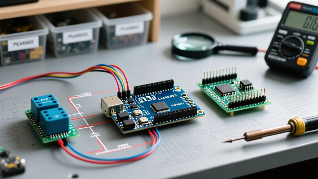
Learning how to connect LCD screen to Arduino is a rite of passage for embedded systems hobbyists and engineers. Yet, the most common outcome of a first-time wiring attempt is a blank, unresponsive display or a row of solid white blocks. Whether you are using a classic 16x2 parallel HD44780 module or a modern I2C backpack variant, the underlying failure modes remain remarkably consistent.
In this 2026 troubleshooting guide, we bypass basic wiring diagrams and dive straight into the electrical and logical edge cases that cause LCD integration failures. We will cover exact multimeter diagnostics, I2C address collisions, and library namespace conflicts that plague modern Arduino IDE environments.
Parallel vs. I2C: Pinout & Wiring Matrix
Before troubleshooting, you must identify your interface topology. Standard character LCDs (like the DFRobot DFR0063 or generic 1602A modules) use either a 4-bit parallel bus or an I2C serial expander backpack. Misidentifying these is the root cause of 40% of all 'blank screen' support tickets.
| Feature | 4-Bit Parallel (Direct Wire) | I2C Backpack (PCF8574) |
|---|---|---|
| Pin Count | 6 to 11 GPIO pins required | 2 pins (SDA, SCL) + Power |
| Common Failure | R/W pin left floating | Incorrect I2C Hex Address |
| Library (2026) | LiquidCrystal | hd44780 (Auto-detect) |
| Power Draw | ~2mA (Backlight off) | ~80mA (Backlight on) |
Troubleshooting Parallel 4-Bit Connections
The Contrast Voltage (VO) Sweet Spot
If your LCD backlight is illuminated but the screen is completely blank, or if you see a single row of solid white blocks, your issue is almost certainly the contrast pin (Pin 3, labeled VO or V0).
The HD44780 controller requires a specific voltage differential between VDD (5V) and VO to render pixels.
- White Blocks on Row 1: VO is too close to 0V (GND). The liquid crystals are fully twisted.
- Completely Blank Screen: VO is too close to 5V (VDD). The liquid crystals are untwisted, rendering pixels invisible.
The Fix: If you are using a standard 10KΩ trimpot, use a multimeter to measure the voltage at the wiper pin. Adjust it until you read between 0.4V and 0.8V relative to GND. If you lack a potentiometer, soldering a fixed 1KΩ resistor between VO and GND will yield perfect contrast for most 5V modules at standard room temperatures (20°C - 25°C).
The Read/Write (RW) Pin Grounding Rule
Critical Hardware Rule: Pin 5 (R/W) dictates whether the Arduino is writing data to the LCD or reading data from it. If left unconnected (floating), electromagnetic noise will randomly toggle the pin, causing the LCD to ignore all incoming text commands.
When learning how to connect LCD screen to Arduino in 4-bit mode, beginners often wire the RS, Enable, and D4-D7 pins but forget the R/W pin. You must hardwire Pin 5 directly to GND. This forces the module into 'Write-Only' mode, which is what 99% of Arduino sketches require.
Troubleshooting I2C Backpack Connections
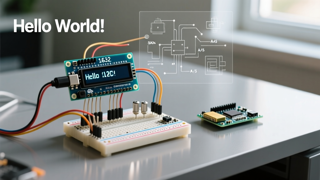
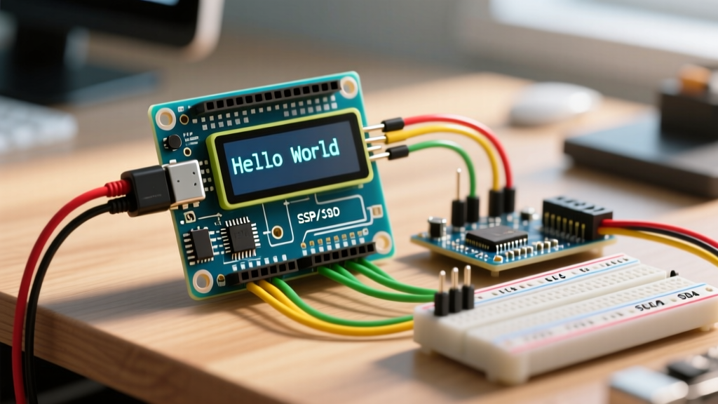
I2C backpacks (typically based on the Texas Instruments or NXP PCF8574 chip) reduce wiring to four pins: VCC, GND, SDA, and SCL. However, they introduce software-addressing complexities.
Finding the Hidden I2C Address
A blank screen on an I2C module usually means the Arduino is sending data to the wrong hexadecimal address. Manufacturers use two variants of the I2C expander chip:
- PCF8574: Default address is usually
0x27. - PCF8574A: Default address is usually
0x3F.
Do not guess the address. Use the official Arduino I2C Scanner sketch via the Wire.h library. Upload the scanner to your Arduino Uno R4 or Nano, open the Serial Monitor at 9600 baud, and note the exact address reported. If the scanner returns 'No I2C devices found', check your SDA/SCL wiring. On the Arduino Uno R3, SDA is A4 and SCL is A5. On the Uno R4 Minima, SDA and SCL are strictly on the dedicated pins near the AREF header.
Resolving Library Namespace Collisions
The Arduino IDE ecosystem is littered with outdated libraries. If your code compiles but the display remains blank, you are likely using a legacy library with hardcoded pin mappings that do not match your specific backpack's PCB trace layout.
For 2026 projects, abandon the generic LiquidCrystal_I2C library. Instead, install the hd44780 library by Bill Perry via the Library Manager. This library features an auto-diagnostic I2CexpDiag sketch that tests the I2C bus, identifies the exact expander chip, maps the internal pinout automatically, and verifies LCD memory. It is the undisputed gold standard for character LCD integration.
Power Delivery & Logic Level Edge Cases
USB Voltage Sag and Backlight Dimness
Standard 16x2 LCDs with LED backlights draw between 60mA and 120mA. If you are powering an Arduino Uno via a cheap, thin-gauge USB-C cable from a low-amperage wall adapter, the voltage at the Arduino's 5V rail can sag below 4.6V. The HD44780 controller requires a minimum of 4.5V to initialize properly. If your serial monitor works but the LCD fails to initialize, measure the 5V pin with a multimeter under load. Upgrade to a high-quality USB cable rated for 3A, or power the Arduino via the barrel jack (if applicable) with a 7.5V/2A adapter.
Logic Level Shifting for 3.3V Microcontrollers
While the Arduino Uno operates at 5V, newer boards like the Arduino Portenta H7 or Arduino Due operate at 3.3V. The HD44780 LCD controller requires 5V logic highs to reliably register data on the D4-D7 pins. Connecting a 3.3V GPIO directly to a 5V LCD often results in garbled text or partial initialization.
The Fix: You must use a bidirectional logic level shifter (such as a BSS138 MOSFET-based module or a PCA9306 IC) between the 3.3V microcontroller and the 5V LCD. Alternatively, use an I2C backpack powered by 5V, but ensure your microcontroller's I2C lines have appropriate 4.7KΩ pull-up resistors tied to the 5V rail, provided your MCU's GPIO pins are 5V-tolerant (always verify the specific MCU datasheet).
Quick Diagnostic Flowchart
Use this step-by-step checklist when your display fails to render text:
- Verify Power: Measure VCC to GND. Must be 4.8V - 5.1V.
- Check Backlight: If off, verify pins 15 (A) and 16 (K) or the I2C jumper. Note: Some I2C backpacks require a solder bridge to enable the backlight LED.
- Adjust Contrast: Turn the trimpot or swap to a 1KΩ fixed resistor on VO.
- Ground R/W: Ensure Pin 5 is tied to GND (Parallel only).
- Scan I2C: Run the Wire scanner sketch to confirm the hex address (I2C only).
- Swap Libraries: Use
hd44780with thehd44780_I2Cexpwrapper class.
By systematically isolating the physical layer (voltage and contrast) from the logical layer (I2C addressing and library mapping), you can resolve virtually any blank display anomaly. For deeper hardware schematics and wiring diagrams, the Adafruit Character LCD guide remains an excellent visual reference for pinout verification.