
Introduction to IR Proximity Detection
Integrating an IR proximity sensor Arduino setup is a rite of passage for robotics and automation hobbyists. Whether you are building a line-following robot, an automatic soap dispenser, or a collision-avoidance rover, infrared (IR) proximity sensors offer a low-cost, reliable method for detecting nearby objects without physical contact. However, beginners often struggle with erratic readings, false triggers, and confusion between analog and digital outputs.
In this comprehensive guide, we will dissect the most common IR proximity modules on the market in 2026, walk through exact wiring schematics for modern boards like the Arduino Uno R4 Minima, and provide production-ready code. We will also cover the real-world physics of IR reflectivity and ambient light interference that most basic tutorials ignore.
Choosing Your Hardware: FC-51 vs. TCRT5000 vs. Sharp GP2Y
Not all IR sensors are created equal. The market is flooded with variations, but they generally fall into three categories. Understanding the difference is critical for your project's success.
| Module / Sensor | Output Type | Typical Range | Avg. Price (2026) | Best Use Case |
|---|---|---|---|---|
| FC-51 | Digital (LM393) | 2cm - 8cm | $1.50 - $2.50 | Simple obstacle avoidance, limit switches |
| TCRT5000 (Raw) | Analog & Digital | 1cm - 15cm | $1.00 - $2.00 | Line following, edge detection, custom PCBs |
| Sharp GP2Y0A21YK0F | Analog (Distance) | 10cm - 80cm | $9.00 - $13.00 | Precise distance mapping, SLAM robotics |
For this tutorial, we will focus primarily on the FC-51 and TCRT5000 modules, as they represent 90% of beginner IR proximity sensor Arduino projects due to their affordability and simplicity.
The Anatomy of the FC-51 Module
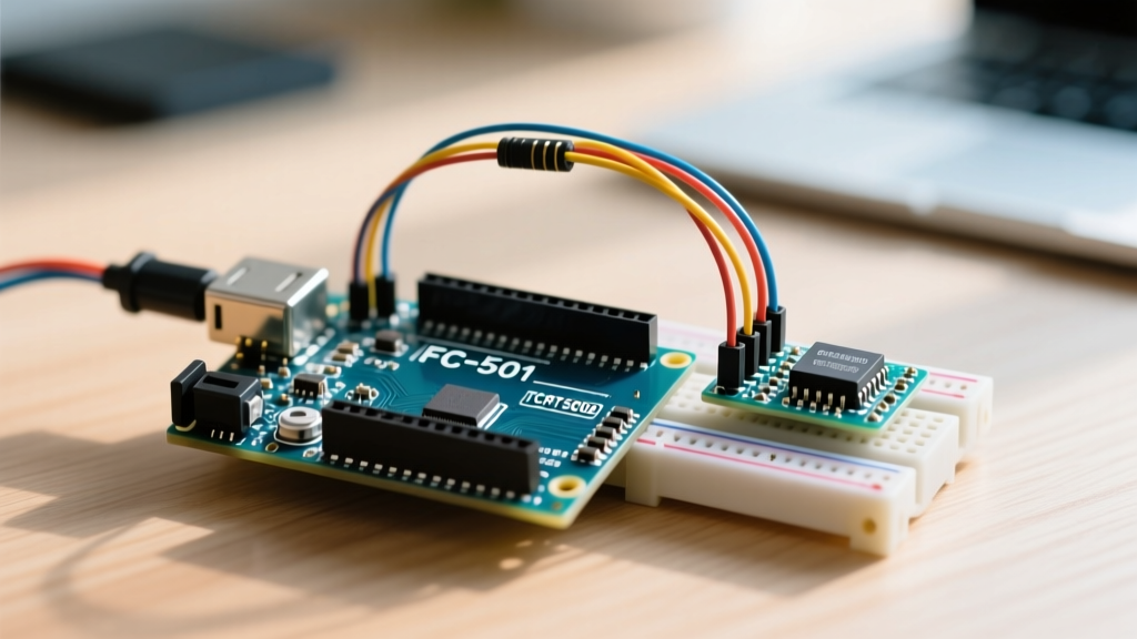
The FC-51 is essentially a breakout board for the TCRT5000 reflective optical sensor. It pairs the raw IR LED and phototransistor with an LM393 dual differential comparator.
Expert Insight: The LM393 comparator features an open-collector output. This means it can only pull the signal line LOW (to ground) and cannot drive it HIGH. The FC-51 module includes a 10kΩ pull-up resistor on the board to handle the HIGH state, but if you ever wire a raw TCRT5000 directly to a microcontroller, you must enable the Arduino's internal pull-up resistors or add an external one to avoid floating pin states.
The module features a blue trimpot (potentiometer) that adjusts the threshold voltage on the comparator's inverting input. By turning this screw, you calibrate the exact distance at which the digital output (DO) flips from HIGH to LOW.
Step-by-Step Wiring Guide
Wiring an IR proximity sensor to an Arduino is straightforward, but power supply noise can ruin your readings. Always use the 5V pin on your Arduino Uno R3 or R4, as the IR LED requires roughly 20mA of current, which can cause brownouts if pulled from a weak 3.3V regulator.
Digital-Only Setup (FC-51 DO Pin)
- VCC to Arduino 5V
- GND to Arduino GND
- DO to Arduino Digital Pin 2 (Interrupt capable)
Analog + Digital Setup (Raw TCRT5000 or FC-51 AO Pin)
- VCC to Arduino 5V
- GND to Arduino GND
- DO to Arduino Digital Pin 2
- AO to Arduino Analog Pin A0
Note: The Analog Out (AO) pin bypasses the LM393 comparator and feeds the raw voltage from the phototransistor's voltage divider directly to the Arduino's ADC. This allows you to measure relative distance based on reflectivity intensity.
Writing the Arduino Code
Below is a robust sketch that reads both the digital trigger and the analog reflectivity value. It includes a simple software debouncing mechanism to prevent rapid state fluttering when an object is exactly on the threshold edge.
// IR Proximity Sensor Arduino Interfacing Code
const int DIGITAL_PIN = 2;
const int ANALOG_PIN = A0;
const int LED_INDICATOR = 13;

int lastState = HIGH;
unsigned long lastDebounceTime = 0;
const unsigned long debounceDelay = 50; // 50ms debounce

void setup() {
  Serial.begin(115200);
  pinMode(DIGITAL_PIN, INPUT);
  pinMode(LED_INDICATOR, OUTPUT);
  Serial.println('IR Proximity Sensor Initialized...');
}

void loop() {
  // Read Analog Value (0-1023)
  int rawAnalog = analogRead(ANALOG_PIN);

  // Read Digital Value with Debounce Logic
  int currentReading = digitalRead(DIGITAL_PIN);

  if (currentReading != lastState) {
    lastDebounceTime = millis();
  }

  if ((millis() - lastDebounceTime) > debounceDelay) {
    if (currentReading == LOW) { // LM393 pulls LOW on detection
      digitalWrite(LED_INDICATOR, HIGH);
      Serial.println('OBSTACLE DETECTED (Digital)');
    } else {
      digitalWrite(LED_INDICATOR, LOW);
    }
  }

  lastState = currentReading;

  // Print Analog Reflectivity Data
  Serial.print(' | Raw Analog Reflectivity: ');
  Serial.println(rawAnalog);

  delay(100); // Poll every 100ms
}
For deeper understanding of how the microcontroller handles pin states, refer to the official Arduino digitalRead() documentation.
Real-World Troubleshooting & Edge Cases
Simulators and sterile lab benches rarely reflect real-world conditions. When deploying your IR proximity sensor Arduino project into the wild, you will encounter physics-based limitations. Here is how to engineer around them.
1. Ambient Sunlight Saturation
Sunlight contains a massive spectrum of infrared radiation. If your sensor is facing a window or operating outdoors, the sun's IR photons will saturate the phototransistor. The sensor will act as if an object is permanently pressed against it (DO stays LOW, AO reads near 0).
The Fix: The FC-51 uses unmodulated IR. To fix this, you must either build a physical 3D-printed shroud (hood) around the sensor to block off-axis light, or upgrade to a modulated 38kHz IR sensor system (like the TSOP38238 receiver paired with a 555 timer or PWM-driven IR LED) which filters out constant ambient IR.
2. Surface Reflectivity and Color Bias
IR proximity sensors do not measure 'distance' directly; they measure reflected light intensity. White printer paper reflects up to 90% of near-infrared light, while matte black electrical tape absorbs it. An object wrapped in black tape might need to be 1cm away to trigger the sensor, whereas a white wall will trigger it at 8cm.
The Fix: If you are building a line-following robot, calibrate your trimpot on the actual track surface. For analog reads, implement a baseline calibration routine in your setup() function that averages 50 reads of the 'floor' state before the robot begins moving.
3. 50Hz/60Hz Mains Flicker Interference
Fluorescent and LED room lighting flicker at 100Hz or 120Hz (twice the AC mains frequency). While human eyes cannot see this, the high-speed phototransistor can, leading to noisy analog readings.
The Fix: Add a 10µF electrolytic capacitor across the VCC and GND pins of the sensor module to smooth out power rail ripple, and use a moving-average software filter in your code to smooth the analog data stream.
Frequently Asked Questions
Can I power the FC-51 with 3.3V on an ESP32?
Yes, but with caveats. The IR LED will emit less light, reducing your maximum range by roughly 40%. Furthermore, the LM393 comparator on cheap clone boards may not output a clean 3.3V HIGH signal when powered by 3.3V due to voltage drop across the internal circuitry. For 3.3V logic boards, it is highly recommended to power the module with 5V but use a logic level shifter or a simple resistor voltage divider on the DO pin to protect your ESP32 GPIO.
Why is my digital pin always reading LOW?
This usually indicates one of three things: The sensor is saturated by ambient sunlight, the trimpot is turned entirely to the 'always trigger' extreme, or the object in front of the sensor is highly reflective and sitting within the minimum blind spot (usually <1cm). Turn the blue trimpot counter-clockwise until the onboard LED turns off, then slowly test with your target object.
How do I increase the detection range beyond 8cm?
The FC-51 is physically limited by its LED wattage and phototransistor sensitivity. You cannot safely push more current through the onboard IR LED without risking thermal failure. If you need ranges between 10cm and 80cm, abandon the FC-51 and purchase a Sharp GP2Y0A21YK0F IR distance sensor, which uses a focused lens and a PSD (Position Sensitive Detector) array rather than simple reflectivity.
Final Thoughts
Mastering the IR proximity sensor Arduino interface requires moving beyond basic digital reads. By understanding the LM393 comparator's open-collector nature, accounting for surface reflectivity, and implementing software debouncing, you transition from a beginner copying code to an engineer designing robust embedded systems. Whether you are automating a smart home fixture or building an autonomous rover, these foundational principles will ensure your sensors perform reliably in the real world.