
Decoding the L293D Motor Driver Shield Arduino Datasheet
If you have built a wheeled robot or an automated pan-tilt camera mount in the last decade, you have likely used an l293d motor driver shield arduino setup. Despite the rise of modern MOSFET-based drivers like the TB6612FNG or TI's DRV8871 in 2026, the L293D shield remains a ubiquitous staple in educational kits, legacy robotics, and DIY prototyping. Its rugged 5V TTL logic compatibility and built-in flyback diodes make it incredibly forgiving for beginners.
However, treating the L293D as an infinite current sink is a fast track to melted solder joints and fried microcontrollers. In this datasheet explainer, we bypass the marketing fluff and translate the official Texas Instruments L293/L293D Datasheet into practical, real-world engineering constraints for your Arduino projects.
Inside the Silicon: BJT H-Bridge Topology
The L293D is not a MOSFET driver; it is a Bipolar Junction Transistor (BJT) based H-bridge. This distinction is critical because BJTs suffer from a fixed saturation voltage drop ($V_{CE(sat)}$), whereas MOSFETs have a resistive drop ($R_{DS(on)}$). When current flows through the L293D, it must pass through two BJT junctions (one high-side, one low-side).
According to the datasheet, this results in a typical voltage drop of 1.4V at 1A, and up to 2.0V at higher currents. If you power a 6V DC motor with a 6V battery pack through this shield, your motor will only see roughly 4.2V to 4.6V. This voltage drop is the primary reason why L293D shields are inefficient for low-voltage, high-current battery-operated robots.
IC Comparison: L293D vs. The Upgrades
Before we dive into thermal limits, it is worth noting that the L293D footprint is shared with other ICs. If your project demands more current, you can physically desolder the L293D and drop in a pin-compatible alternative.
| IC Model | Continuous Current / Channel | Peak Current | Internal Diodes? | Typical Voltage Drop |
|---|---|---|---|---|
| L293D | 600 mA | 1.2 A | Yes | ~1.4V at 1A |
| SN754410 (TI) | 1.0 A | 2.0 A | No (External needed) | ~1.2V at 1A |
| L298N (Different footprint) | 2.0 A | 3.0 A | No (External needed) | ~2.0V at 2A |
Note: If upgrading to the SN754410 on a generic shield, you must add external Schottky flyback diodes, as the SN754410 lacks the internal clamp diodes found in the 'D' variant of the L293.
Absolute Maximum Ratings & Thermal Math
Section 6 of the TI datasheet outlines the Absolute Maximum Ratings. The most misunderstood parameter is the supply voltage. The L293D features two separate power rails:
- VCC1 (Logic Supply): Powers the internal logic gates. Max 36V, but typically tied to the Arduino's 5V rail.
- VCC2 (Motor Supply): Powers the H-bridge outputs. Max 36V.
The Thermal Reality Check
The datasheet claims a continuous output current of 600 mA per channel. Let us run the thermal math using the datasheet's thermal impedance data for the standard 16-pin DIP package (which most shields use).
Thermal Dissipation Calculation at 600mA:
Voltage Drop ($V_{drop}$) = ~1.2V (at 600mA)
Power Dissipated per Channel ($P_d$) = 1.2V × 0.6A = 0.72W
Total Power (2 channels active) = 1.44W
Junction-to-Ambient Thermal Resistance ($\theta_{JA}$) = ~80°C/W
Temperature Rise = 1.44W × 80°C/W = 115.2°C above ambient.
If your room is 25°C, the silicon junction will hit roughly 140°C. The L293D features internal thermal shutdown that triggers around 150°C. Therefore, running two motors at a continuous 600mA without active cooling will push the IC into thermal throttling. In practical 2026 robotics design, you should limit continuous draw to 300mA - 400mA per channel on a passively cooled shield.
Shield Pinout Mapping: Translating Datasheet to Arduino
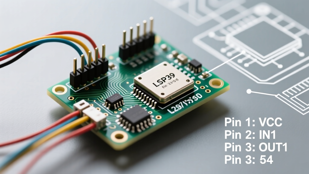
Generic L293D shields and the legacy Adafruit Motor Shield V1 route the IC pins to specific Arduino Uno headers. Understanding this mapping is crucial if you want to bypass bulky libraries and write direct PORT register manipulations for high-frequency PWM.
- Enable Pins (1,2EN and 3,4EN): Typically routed to Arduino PWM pins (e.g., D5 and D6 on Uno) to control motor speed via analogWrite().
- Input Pins (1A, 2A, 3A, 4A): Routed to standard digital pins (e.g., D4, D7, D8, D12) to dictate H-bridge polarity (forward/reverse).
- Logic VCC (VCC1): Jumpered to the Arduino 5V pin.
- Motor VCC (VCC2): Connected to the shield's green screw terminals (often labeled EXT_PWR or VIN).
⚠️ Critical Datasheet Note on Decoupling: The datasheet heavily emphasizes placing 100nF ceramic capacitors as close to VCC1 and VCC2 as possible. Most cheap clone shields skimp on VCC2 decoupling. If your Arduino resets randomly when a motor starts, it is because the motor's inrush current is causing a ground bounce or voltage droop that resets the ATmega328P. Soldering an extra 100µF electrolytic capacitor directly across the shield's motor power terminals solves 90% of these brownout issues.
The Internal Flyback Diode Advantage
Section 8.2 of the datasheet highlights the integrated clamp diodes. When an inductive load (like a DC motor) is suddenly turned off, the collapsing magnetic field generates a massive reverse voltage spike (Back-EMF). Without a path to dissipate, this spike will punch through the BJT junctions, destroying the IC.
The 'D' in L293D signifies the inclusion of these internal diodes. While they are slightly slower than external Schottky diodes (like the 1N5819), they are perfectly adequate for the sub-1kHz PWM frequencies typically generated by Arduino's default `analogWrite()` function (which runs at ~490Hz on most pins). This integration is exactly why the L293D shield requires fewer external components and remains a favorite for rapid prototyping.
Real-World Troubleshooting & Edge Cases
When your l293d motor driver shield arduino project fails, use this datasheet-backed troubleshooting sequence:
- Motor whines but does not turn: You are likely hitting the stall current limit. A standard 130-size toy motor can draw 1.5A at stall. The L293D's internal thermal protection or current limiting is engaging. Measure the stall current with a multimeter; if it exceeds 1A, you need a larger driver or a gearbox reduction.
- Shield gets too hot to touch: As proven in our thermal math, this is normal for BJT drivers at >400mA. If it smells like burning plastic, the IC is exceeding its 150°C junction limit. Add a small 5V heatsink fan or switch to a MOSFET shield.
- Arduino logic behaves erratically: You have crossed the logic and motor grounds. Ensure the GND pins on the shield are firmly seated. The L293D requires a common ground reference between VCC1 (Logic) and VCC2 (Motor) to interpret the 5V TTL signals correctly.
- PWM causes audible squealing: The default Arduino PWM frequency is in the human hearing range. Use the `Tone` library or manipulate Timer1 registers to push the PWM frequency above 20kHz. The L293D datasheet confirms it supports switching frequencies up to 5kHz reliably, but pushing to 20kHz may increase switching losses and heat.
Final Verdict for 2026 Makers
The L293D motor driver shield is a masterclass in legacy engineering. It is not the most efficient, nor the coolest-running driver on the market today. However, its absolute resilience to wiring mistakes, integrated flyback protection, and seamless 5V logic interfacing make it an unparalleled learning tool. By respecting the thermal limits and voltage drops outlined in the TI datasheet, you can reliably deploy L293D shields in everything to autonomous rovers to automated greenhouse vents.