
The 2026 Arduino Light Sensor Landscape
When designing an automated lighting system, a sun-tracking solar array, or a precision photography light meter, selecting the correct Arduino light sensor is a foundational decision. The market has evolved significantly. While the traditional Cadmium Sulfide (CdS) photoresistor was once the undisputed default, strict RoHS enforcement in 2026 has severely restricted its availability in North American and European markets. Today, makers and engineers must choose between legacy analog silicon alternatives and modern digital I2C luminosity sensors.
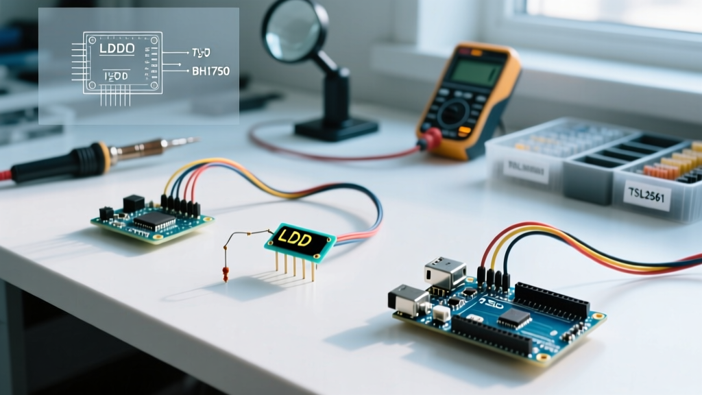
In this comprehensive component comparison, we dissect the three most popular architectures for Arduino light sensing: the analog GL5528 / TEMT6000 Photoresistors, the digital BH1750FVI, and the high-dynamic-range TSL2561. We will evaluate them on spectral response, I2C bus behavior, real-world pricing, and the specific failure modes that ruin weekend projects.
Specification & Pricing Matrix
Before diving into circuit design, here is a high-level comparison of the three dominant sensor modules available to Arduino developers today. Pricing reflects average 2026 market rates for pre-wired breakout boards from reputable vendors.
| Feature | Analog LDR (GL5528 / TEMT6000) | BH1750FVI (Digital) | TSL2561 (Digital) |
|---|---|---|---|
| Interface | Analog (Voltage Divider) | I2C | I2C / SMBus |
| Output Metric | Relative Resistance / Voltage | Direct Lux (1 to 4 lux res.) | Raw IR + Broadband Counts |
| Lux Range | N/A (Non-linear) | 1 - 65,535 lux | 0.1 - 40,000+ lux |
| Module Price (2026) | $0.15 - $0.80 | $1.80 - $2.50 | $3.50 - $5.50 |
| Best Application | Basic day/night triggers | Indoor lighting automation | Outdoor / Direct sunlight |
The Analog Legacy: Photoresistors (LDR & TEMT6000)
The classic Light Dependent Resistor (LDR) operates on the principle of photoconductivity. When photons strike the semiconductor material, electron-hole pairs are generated, dropping the electrical resistance. The ubiquitous GL5528 peaks at a 540nm wavelength (green light) and drops from ~1MΩ in total darkness to ~10kΩ at 10 lux.
The RoHS Problem and the TEMT6000 Shift
Because traditional LDRs rely on toxic Cadmium Sulfide (CdS), they are non-compliant with modern environmental standards. If you are designing a commercial product or sourcing parts in the EU, you must pivot to silicon phototransistors like the TEMT6000X01. The TEMT6000 mimics the human eye's spectral response (peaking at 570nm) and outputs a linear analog current proportional to ambient light, which is easily converted to voltage using a standard 10kΩ pull-down resistor.
Analog Wiring & The Voltage Divider
To interface an analog light sensor with an Arduino's 10-bit ADC (0-1023), you must build a voltage divider. The formula governing your analog read is:
V_out = V_cc * (R_fixed / (R_sensor + R_fixed))
Expert Tip: Do not use a 10kΩ fixed resistor if your sensor will be used outdoors. In direct sunlight (100,000 lux), an LDR's resistance can drop below 500Ω, rendering a 10kΩ pull-down virtually useless and compressing all your readable data into the bottom 5% of the ADC range. Swap to a 1kΩ or 470Ω resistor for outdoor solar-tracking applications.
BH1750FVI: The I2C Lux Standard
Manufactured by ROHM Semiconductor, the BH1750FVI is the workhorse of indoor Arduino light sensor projects. Unlike analog sensors that require you to map arbitrary voltage values to estimated lux, the BH1750 contains an internal photodiode, an integrating ADC, and an I2C interface that outputs a direct 16-bit lux value.
Resolution Modes and Integration Times
As detailed in the SparkFun BH1750 Hookup Guide, the sensor features three primary measurement modes. The most common is Continuously High-Resolution Mode, which provides a 1-lux resolution with a 120ms integration time. If you are measuring very dim environments (like a home theater or starlight conditions), you can switch to High-Resolution Mode 2, which halves the measurement range but doubles the resolution to 0.5 lux by extending the integration window.
I2C Addressing Quirks
The BH1750 supports two I2C addresses: 0x23 (default, ADDR pin floating/low) and 0x5C (ADDR pin tied to VCC). A common failure mode on cheap clone boards is the omission of the physical ADDR pin breakout, locking you to 0x23 and preventing you from running two sensors on the same I2C bus without a multiplexer like the TCA9548A.
TSL2561: The High-Dynamic Range Specialist
For outdoor applications, greenhouse automation, or UV/IR-heavy environments, the TSL2561 (originally by TAOS, now ams OSRAM) is the superior Arduino light sensor. According to the Adafruit TSL2561 Tutorial, its secret weapon is a dual-photodiode architecture.
Dual-Channel Spectral Separation
The TSL2561 features two distinct sensing channels:
- Channel 0 (Broadband): Measures visible light PLUS infrared (IR) light.
- Channel 1 (Infrared): Measures ONLY infrared light.
By reading both channels and applying a piecewise linear approximation algorithm (detailed in the official datasheet), the Arduino can subtract the IR interference from the Broadband reading. This yields a highly accurate visible-light lux value, even under harsh halogen or direct sunlight conditions where IR radiation would normally blind a standard single-diode sensor.
Gain Settings and Saturation
The TSL2561 allows software-configurable gain (1x or 16x). A frequent edge case occurs when makers leave the sensor on 16x gain outdoors. The ADC will saturate at 65,535 counts in milliseconds, resulting in a hardcoded '0 lux' error return in standard libraries. Always implement an auto-ranging function in your firmware that drops the gain to 1x if Channel 0 exceeds 40,000 counts.
Real-World Failure Modes & Edge Cases
Bench testing rarely reflects field conditions. Here are the hidden traps associated with Arduino light sensors that you must engineer around:
1. The Missing I2C Pull-Up Resistor
Both the BH1750 and TSL2561 rely on I2C. While premium breakout boards include 4.7kΩ surface-mount pull-up resistors on the SDA and SCL lines, budget marketplace modules often omit them to save $0.02 per unit. Without pull-ups, the I2C lines float, resulting in intermittent 'Wire.h' timeout errors or random 0 lux readings. Always verify your breakout board schematic; if pull-ups are missing, wire external 4.7kΩ resistors from SDA/SCL to 3.3V.
2. Automotive Glass and IR Attenuation
If you are building a dashboard-mounted sun tracker or an automatic headlight controller, be aware that modern automotive windshields feature heavy UV and IR blocking tints. A TSL2561 mounted inside a car will read drastically different IR ratios than one mounted outside, skewing the internal lux calculation algorithm. In these scenarios, calibrate your software's IR-compensation ratio manually using a reference lux meter.
3. 50Hz/60Hz Mains Flicker Aliasing
Fluorescent and cheap LED bulbs flicker at twice the AC mains frequency (100Hz or 120Hz). Analog LDRs have a slow response time (~20ms), which naturally averages out this flicker. However, if you use a fast-sampling silicon phototransistor (like the TEMT6000) with a high-speed ADC read loop, your Arduino will capture the peaks and valleys of the flicker, causing wild swings in your data. Use a 1µF capacitor in parallel with your analog sensor's pull-down resistor to create a low-pass filter that smooths out AC flicker.
Decision Framework: Which Sensor Should You Choose?
Use this quick-reference guide to finalize your Bill of Materials (BOM):
- Choose the Analog TEMT6000/LDR if: You are building a simple day/night trigger for a relay, you have no available I2C pins, or your BOM budget is strictly under $1.00.
- Choose the BH1750 if: You are designing indoor smart-home lighting, automated blinds, or display brightness dimmers where direct, human-eye-calibrated lux readings are required without complex math.
- Choose the TSL2561 if: Your project operates outdoors, requires high-dynamic-range measurement (from starlight to direct noon sun), or involves environments with heavy IR-emitting artificial lights.
Frequently Asked Questions
Can I power these sensors with 5V?
The analog LDR is a passive resistor and doesn't care about voltage (within reason). However, both the BH1750 and TSL2561 are strictly 3.3V logic devices. While some breakout boards feature onboard 3.3V LDO regulators allowing you to feed them 5V on the VIN pin, the I2C SDA/SCL data lines will still output 3.3V. This is generally safe for 5V Arduino Uno inputs, but if you are using a 3.3V microcontroller like the ESP32 or Arduino Nano 33 IoT, always wire the power directly to the 3.3V pin to avoid back-feeding the LDO.
How do I convert analog reads to actual Lux?
According to photometric standards outlined by the National Institute of Standards and Technology (NIST), lux is a measure of luminous flux per unit area. Because analog LDRs have a logarithmic, non-linear resistance curve that varies wildly between manufacturing batches, converting an analog 0-1023 read to true lux requires bench-calibrating your specific resistor against a known commercial lux meter and plotting a logarithmic regression curve in your code. If you need true lux without calibration, use the BH1750.