
Mastering PIR and Arduino Integration for Reliable Motion Detection
Integrating a Passive Infrared (PIR) sensor with a microcontroller is a foundational skill in embedded systems, yet achieving flawless, false-trigger-free operation requires moving beyond basic tutorials. The HC-SR501 module, paired with an Arduino Uno R4 Minima or Nano Every, remains the industry standard for DIY occupancy detection in 2026. Priced between $1.50 and $3.00 per unit, it offers incredible value. However, out-of-the-box implementations frequently suffer from thermal drift, RF interference, and improper timing logic.
This guide provides a deep-dive, expert-level approach to wiring, hardware calibration, and event-driven C++ coding for the HC-SR501, ensuring your motion detection system is robust enough for real-world deployment.
Anatomy of the HC-SR501: Beyond the Plastic Dome
To troubleshoot effectively, you must understand the hardware. The HC-SR501 relies on a D203S dual-element pyroelectric sensor housed beneath a high-density polyethylene (HDPE) Fresnel lens. This lens fractures the detection zone into alternating positive and negative infrared segments. Motion is only detected when a heat source (like a human body at ~34°C) crosses these segments, creating a differential voltage spike.
This analog spike is processed by the BISS0001 Micro Power PIR Motion Detector IC. The BISS0001 handles the signal amplification, bandpass filtering, and timing logic, outputting a clean 3.3V digital HIGH signal on the OUT pin when motion is confirmed. Understanding this pipeline is critical for diagnosing 'ghost triggers' and timing anomalies.
Precision Wiring & Logic Level Considerations
While the HC-SR501 is marketed as a 5V module, its internal BISS0001 chip operates at 3.3V via an onboard LDO regulator. The digital output pin will typically output between 3.0V and 3.5V when HIGH. This makes it natively compatible with 5V Arduinos (which recognize anything above 3.0V as HIGH) and 3.3V microcontrollers like the ESP32 or Arduino Nano 33 IoT.
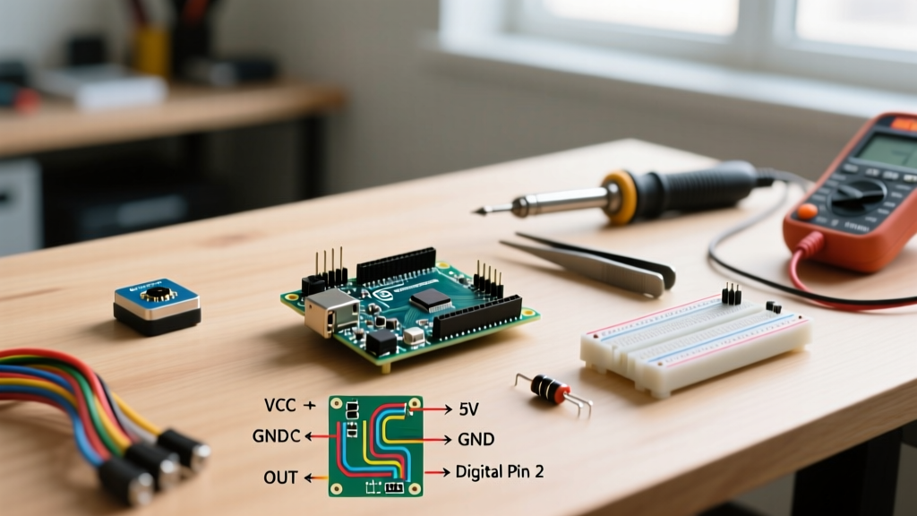
| HC-SR501 Pin | Arduino Uno R4 (5V) | ESP32 / Nano 33 IoT (3.3V) | Expert Notes & Edge Cases |
|---|---|---|---|
| VCC | 5V | 5V (VIN) | Do not power via 3.3V. The onboard LDO requires a minimum 4.5V input to regulate properly. |
| OUT | Pin 2 (Interrupt) | GPIO 4 (Interrupt) | Use a hardware interrupt pin to avoid blocking the main loop during long delay cycles. |
| GND | GND | GND | Ensure a shared ground plane. Long ground wires introduce voltage drop and false triggers. |
Pro-Tip for Power Stability: The cheap LDO regulators on clone HC-SR501 boards often introduce power ripple. Soldering a 100µF electrolytic capacitor directly across the VCC and GND pins on the PCB will drastically reduce false triggers caused by voltage sag during Wi-Fi or RF transmission spikes.
Hardware Calibration: Dialing in the BISS0001
The HC-SR501 features two orange trimpots and a three-pin jumper block. Proper physical calibration must precede any software deployment.
1. The Sensitivity Potentiometer (Left)
This adjusts the spatial detection range from roughly 3 meters to 7 meters. Turning it fully clockwise maximizes range but increases susceptibility to thermal noise from HVAC vents. For indoor room occupancy, set it to the 12 o'clock position (approx. 4.5 meters) and physically mask the outer edges of the Fresnel lens with electrical tape if you need to restrict the field of view.
2. The Time Delay Potentiometer (Right)
This dictates how long the OUT pin stays HIGH after motion ceases. The range is logarithmic, spanning from 0.3 seconds (fully counter-clockwise) to roughly 200 seconds (fully clockwise). Set this to the minimum (0.3s) and handle all extended timing logic in your C++ code. Relying on hardware timers makes debugging impossible and locks up the sensor during the timeout period.
3. Trigger Mode Jumper
- H (Repeatable Trigger): The output remains HIGH as long as motion is continuously detected. The timer resets with every new movement.
- L (Non-Repeatable Trigger): The output goes HIGH for the set delay, then goes LOW and ignores all motion for a brief lockout period.
Recommendation: Always use the H (Repeatable) mode by placing the jumper on the top two pins. This ensures no micro-movements are missed during the delay window.
Event-Driven C++ Implementation
Beginner tutorials often use digitalRead() inside a blocking loop(). This is an anti-pattern. According to the Arduino attachInterrupt() documentation, utilizing hardware interrupts allows the microcontroller to perform other tasks (like updating displays or managing network stacks) while instantly capturing motion events.
Furthermore, as noted in the Arduino Debounce Example, sensor signals require software filtering to ignore microsecond noise spikes.
const byte PIR_PIN = 2; // Must be an interrupt-capable pin
const unsigned long DEBOUNCE_DELAY = 50; // 50ms software debounce
const unsigned long COOLDOWN_PERIOD = 5000; // 5s logical cooldown

volatile bool motionFlag = false;
unsigned long lastTriggerTime = 0;
unsigned long lastDebounceTime = 0;

void setup() {
  Serial.begin(115200);
  pinMode(PIR_PIN, INPUT);

  // Attach interrupt on RISING edge
  attachInterrupt(digitalPinToInterrupt(PIR_PIN), motionISR, RISING);

  Serial.println('System Online. Waiting for 30s PIR calibration...');
  // The BISS0001 requires 30-60 seconds to calibrate its baseline IR on boot
  delay(30000);
  Serial.println('Calibration complete. Monitoring...');
}

void loop() {
  unsigned long currentMillis = millis();

  if (motionFlag) {
    motionFlag = false; // Reset flag immediately

    // Software debouncing logic
    if ((currentMillis - lastDebounceTime) > DEBOUNCE_DELAY) {
      lastDebounceTime = currentMillis;

      // Logical cooldown to prevent serial/network flooding
      if ((currentMillis - lastTriggerTime) > COOLDOWN_PERIOD) {
        lastTriggerTime = currentMillis;
        handleMotionEvent(currentMillis);
      }
    }
  }

  // Non-blocking background tasks go here
}

void motionISR() {
  motionFlag = true;
}

void handleMotionEvent(unsigned long timestamp) {
  Serial.print('Occupancy Detected at: ');
  Serial.print(timestamp / 1000);
  Serial.println('s');
  // Trigger relays, MQTT payloads, or log to SD card here
}
Advanced Troubleshooting & Edge Cases
Even with perfect code, environmental physics can disrupt PIR sensors. Here is how to solve the most common field failures:
The 'Ghost Trigger' Phenomenon (RF Interference)
If your Arduino is also driving a 2.4GHz Wi-Fi module (like an ESP8266 or nRF24L01), the RF emissions can couple into the high-impedance analog traces of the BISS0001, causing phantom triggers. The Fix: Create a Faraday shield. Cut a piece of aluminum foil slightly smaller than the HC-SR501 PCB and tape it to the back (component side) of the board. Ground the foil to the module's GND pin. This blocks rear-facing RF noise without obstructing the front-facing Fresnel lens.
Thermal Blindness in Summer Months
PIR sensors do not detect absolute heat; they detect differential heat. If the ambient room temperature rises to match human skin temperature (approx. 34°C / 93°F), the sensor will become entirely blind to human movement. This is a known limitation documented in Adafruit's comprehensive PIR Sensor Guide. The Fix: In un-air-conditioned environments like garages or attics, supplement the HC-SR501 with a 24GHz microwave radar sensor (like the RCWL-0516) which detects physical mass movement regardless of thermal differentials.
The Initialization Lockout Trap
Developers frequently report that their sensor triggers continuously for the first minute after power-on, leading them to believe the module is defective. This is normal behavior. Upon receiving power, the BISS0001 chip takes 30 to 60 seconds to sample the ambient infrared environment and establish a baseline. Any movement during this calibration window will cause erratic output. Always implement a 60-second blocking delay or software ignore-state in your setup() routine.