
The Reality of Ultrasonic Sensing in 2026
Integrating an ultrasonic proximity sensor Arduino setup seems trivial until you encounter phantom readings, zero-distance timeouts, or erratic jumps. Whether you are using the ubiquitous $2.50 HC-SR04, the $8.00 waterproof JSN-SR04T, or the $30.00 industrial MaxBotix MB1010 LV-MaxSonar-EZ1, acoustic sensing is highly susceptible to environmental and electrical noise. As of 2026, the market is flooded with clone modules that often suffer from poor crystal oscillator calibration and noisy voltage regulators. This guide bypasses basic tutorials and dives straight into advanced hardware and software troubleshooting to stabilize your sensor data.
Diagnostic Matrix: Symptom to Root Cause
Before ripping out your breadboard, match your specific failure mode to the diagnostic matrix below. This table covers the most common edge cases encountered in robotics and automation projects.
| Symptom | Probable Hardware Cause | Probable Software Cause | Quick Fix / Action |
|---|---|---|---|
| Constant 0 cm or 0 ms | Missing 5V power, broken Echo trace | Missing trigger pulse delay | Verify VCC with multimeter; add 10us HIGH trigger |
| Constant max timeout value | Echo pin floating, 40kHz transducer cracked | pulseIn timeout set too low | Add 4.7k pull-down on Echo; increase timeout to 30000us |
| Erratic jumps (e.g., 15cm to 200cm) | Acoustic cross-talk, breadboard EMI | No median filtering applied | Use NewPing library median filter; add 100nF decoupling cap |
| Readings halt completely | JSN-SR04T overheating, logic level clash | Blocking pulseIn without timeout | Use non-blocking interrupts; add BSS138 level shifter |
Hardware and Wiring Edge Cases
The 3.3V Logic Trap
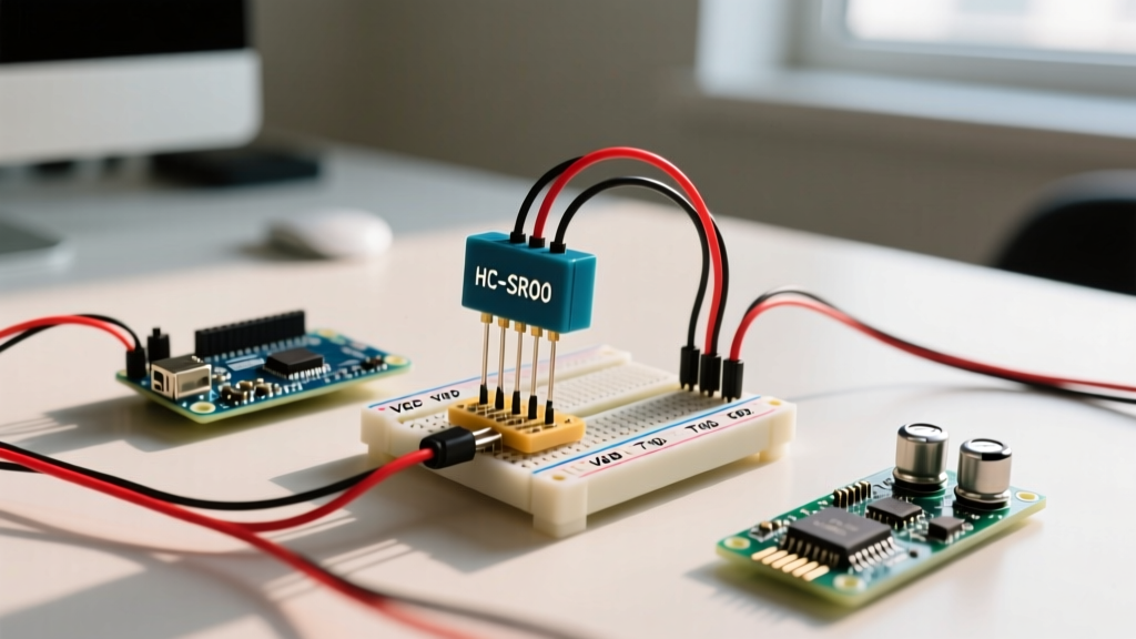
The standard HC-SR04 requires a 5V power supply and outputs a 5V logic HIGH on the Echo pin. If you are using an Arduino Due, Arduino Nano 33 IoT, or any modern 3.3V microcontroller, feeding a 5V Echo signal directly into the GPIO pin will degrade or instantly destroy the MCU's internal protection diodes.
Solution: Do not rely on internal pull-ups. Use a bidirectional logic level converter (like the BSS138-based modules, costing around $1.50) or build a simple voltage divider using a 2kΩ and 3.3kΩ resistor network on the Echo pin to safely step the 5V signal down to 3.2V.
Parasitic Capacitance and EMI on the Echo Pin
When using long jumper wires (over 20cm) on a breadboard, the Echo wire acts as an antenna. It picks up electromagnetic interference (EMI) from the Arduino's onboard 16MHz crystal or nearby switching motor drivers. This manifests as random microsecond spikes, resulting in false short-distance readings.
- Decoupling: Solder a 100nF (0.1µF) ceramic capacitor directly across the VCC and GND pins on the back of the sensor module, not on the breadboard.
- Pull-down Resistor: Install a 4.7kΩ resistor between the Echo pin and GND. This bleeds off parasitic capacitance and forces a clean LOW state between measurements.
- Shielding: Route the Echo wire away from PWM motor control lines and use twisted-pair wiring for the Trigger and GND signals.
Module-Specific Trigger Timing
Not all ultrasonic modules are created equal. While the HC-SR04 requires a standard 10-microsecond HIGH pulse on the Trigger pin, the waterproof JSN-SR04T requires a minimum 20-microsecond pulse. Furthermore, the JSN-SR04T needs a much longer delay between consecutive readings (at least 20ms, compared to the HC-SR04's 60ms cycle) to allow the acoustic ringing to dissipate inside the sealed metal mesh housing.
Acoustic Physics and Environmental Interference
Beam Angle and Specular Reflection
Ultrasonic sensors operate at 40kHz, which translates to a wavelength of roughly 8.5mm in air. The HC-SR04 transducers have a conical beam width of approximately 15 to 30 degrees. If your target is a smooth, hard surface (like glass, polished metal, or glazed tile) positioned at an angle greater than 15 degrees relative to the sensor face, the sound waves will undergo specular reflection—bouncing away from the receiver entirely. The sensor will timeout and report maximum distance.
Expert Tip: If you must detect angled glass or metal surfaces, mount a small piece of acoustic damping foam or matte textured tape on the target area to scatter the 40kHz waves back to the receiver.
Cross-Talk in Multi-Sensor Arrays
Building a 2026 autonomous rover with four HC-SR04 sensors? Firing them simultaneously will result in catastrophic cross-talk, where Sensor A receives the echo from Sensor B's transmission. Because all standard HC-SR04 modules operate at exactly 40kHz, they cannot differentiate between their own pings and those of neighboring sensors.
The Sequential Firing Protocol:
You must fire sensors sequentially with a minimum 35ms delay between each ping. Alternatively, upgrade to the MaxBotix MB1010 LV-MaxSonar-EZ1, which features an automatic daisy-chain mode that synchronizes multiple modules via a single digital pin, eliminating cross-talk entirely without complex software timing.
Software Timing and Code Optimization
PulseIn Timeouts and Blocking Code
The standard Arduino pulseIn() function is blocking. If you call pulseIn(echoPin, HIGH) without a timeout parameter, and the sensor fails to receive an echo, the Arduino will halt execution for a full 1000 milliseconds (1 second) waiting for a signal that will never arrive. This destroys the responsiveness of your control loops.
Actionable Fix: Always define a strict timeout based on the maximum physical range of your sensor. For a 400cm maximum range, the sound wave travels 800cm round-trip. At 343 m/s, this takes roughly 23,300 microseconds. Set your timeout to 25000:
duration = pulseIn(echoPin, HIGH, 25000);
Interrupt-Driven Measurement
For high-speed robotics, polling the Echo pin is inefficient. Utilize Pin Change Interrupts (PCINT) or the NewPing library. NewPing utilizes hardware timers to measure the pulse width in the background, freeing the main loop to handle PID motor calculations and wireless telemetry simultaneously. It also includes a built-in median filter, taking 5 rapid pings, discarding the highest and lowest outliers, and returning the median value.
Advanced Temperature Compensation
Most basic tutorials assume the speed of sound is a constant 343 meters per second. This is only true at exactly 20°C (68°F). According to The Physics Classroom, the speed of sound in air is highly dependent on temperature. If your Arduino robot operates in an unheated warehouse at 5°C, the speed of sound drops to 334 m/s, introducing a 2.6% error in your distance calculations. Over a 3-meter measurement, this equates to nearly 8cm of inaccuracy.
The Compensation Formula
To achieve millimeter-level accuracy, integrate a cheap TMP36 or BME280 temperature sensor into your build and apply the following thermodynamic compensation formula:
- Speed of Sound (v):
v = 331.3 + (0.606 * temperature_in_Celsius) - Distance Calculation:
distance_cm = (duration_us * v) / 20000
By dynamically updating the variable v in every loop iteration based on live BME280 data, your ultrasonic proximity sensor Arduino setup will remain perfectly calibrated whether deployed in a freezing outdoor environment or a hot industrial enclosure.
Summary of Best Practices
Troubleshooting ultrasonic sensors requires looking beyond basic wiring diagrams. By addressing 3.3V logic mismatches, mitigating breadboard EMI with pull-down resistors, enforcing strict pulseIn timeouts, and applying real-time temperature compensation, you can transform an unreliable $2 toy into a precision industrial measurement tool.