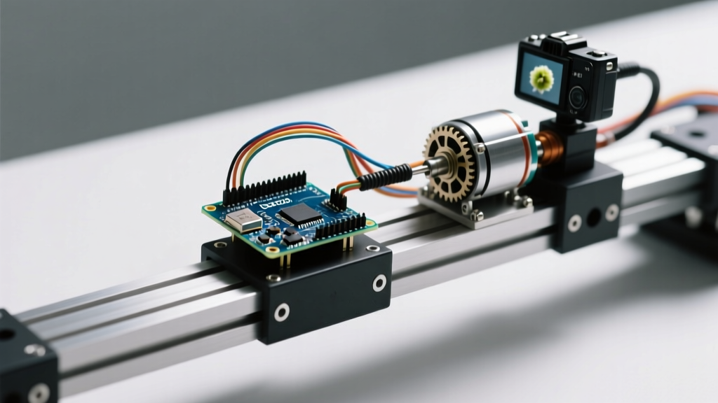

Why Macro Photographers Ditch DC Motors for Steppers
When building an automated focus rail for macro photography or a CNC pen plotter, precision is non-negotiable. Standard DC motors require complex encoder feedback loops to maintain position, while hobby servos suffer from potentiometer jitter that ruins sub-millimeter focus stacking. This is where an arduino stepper motor setup shines. By leveraging open-loop step counting, a microcontroller can command exact physical displacements without the cost and complexity of closed-loop feedback systems.
In this guide, we move beyond the outdated, noisy A4988 drivers of the past decade. For 2026, the gold standard for silent, high-torque motion control in DIY peripherals is the NEMA 17 stepper paired with a Trinamic TMC2209 UART driver, orchestrated by an Arduino Uno R4 Minima. We will walk through the physics, wiring, and firmware architecture required to build a camera slider capable of 0.01mm incremental movements.
Component BOM & Cost Breakdown (2026 Pricing)
Building a reliable motion platform requires matching the motor's inductance to the driver's voltage capabilities. Below is the exact bill of materials used for our reference focus rail build.
| Component | Model / Specification | Role | Approx. Cost |
|---|---|---|---|
| Microcontroller | Arduino Uno R4 Minima (48MHz Cortex-M4F) | Kinematics processing & UART comms | $20.00 |
| Stepper Motor | 17HS4401S (NEMA 17, 1.8°, 1.5A, 4.2kg-cm) | Primary actuator | $12.50 |
| Motor Driver | BigTreeTech TMC2209 V1.2 (UART enabled) | Silent microstepping & stall detection | $6.00 |
| Transmission | T8 Lead Screw (2mm pitch) + Anti-backlash nut | Rotary to linear motion conversion | $9.00 |
| Power Supply | 24V 5A Switching PSU (120W) | High-voltage bus for faster current rise times | $14.00 |
Total estimated peripheral cost: ~$61.50 (excluding aluminum extrusions and 3D printed mounts).
The Physics of Payload and Torque Margins
A common mistake beginners make when interfacing an arduino stepper motor is ignoring the torque curve. Stepper motors do not provide constant torque; their holding torque is highest at stall and drops off exponentially as RPM increases due to the inductance of the motor coils limiting current rise time.
Calculating the Lead Screw Mechanics
Our camera payload is 1.5kg (a standard mirrorless body with a macro lens). We are using a T8 lead screw with a 2mm pitch and a 4mm radius. To calculate the required torque to lift or push this payload horizontally against friction:
- Force (F): 1.5kg × 9.8 m/s² = 14.7 Newtons.
- Lead Screw Efficiency: ~0.9 (with POM anti-backlash nuts).
- Required Torque (T): (F × Pitch) / (2π × Efficiency) = (14.7 × 0.002) / (6.28 × 0.9) ≈ 0.0052 Nm.
The 17HS4401S motor provides 0.41 Nm of holding torque. This gives us a massive safety factor of nearly 78x. Why do we need such a large margin? Because static friction (stiction) in the linear rails and the inertia of accelerating the payload require burst torque. Furthermore, running the motor at 50% of its rated current via the TMC2209 keeps the system completely silent while providing more than enough torque for the application.
Silent Motion: Wiring the TMC2209 via UART
Unlike legacy drivers that rely on analog potentiometers to set the current limit (VREF), the TMC2209 allows digital current configuration via a single-wire UART connection. This eliminates the need to manually tune a tiny screw with a multimeter and prevents thermal drift.
Pro-Tip: Ensure the MS1_AD0 pin on the TMC2209 is bridged to the appropriate pad on the underside of the PCB to enable UART mode. Out of the box, many BTT drivers ship in standalone (step/dir hardware) mode.
Pinout Mapping (Uno R4 Minima to TMC2209)
- VM & GND: Connect to 24V PSU and common ground.
- VDD_IO: Connect to the Arduino's 5V pin (powers the logic level shifters).
- TX (Driver) to RX (Arduino): Connect Driver TX to Arduino Pin 0 (RX). Note: The TMC2209 uses a single-wire UART protocol, but separating TX/RX via a 1k resistor on the RX line prevents bus contention.
- RX (Driver) to TX (Arduino): Connect Driver RX to Arduino Pin 1 (TX) through a 1kΩ resistor.
- STEP & DIR: Connect to Arduino Pins 3 and 4, respectively.
- 1A, 1B, 2A, 2B: Connect to the NEMA 17 coil pairs (verify coil pairing with a multimeter continuity test before powering on).
Firmware Architecture: AccelStepper Meets TMCStepper
To achieve professional-grade motion profiles, we combine two powerful libraries. The AccelStepper library handles the trapezoidal acceleration ramps, ensuring the motor doesn't stall when starting or stopping heavy payloads. Meanwhile, the TMCStepper library handles the silent chopping algorithms.
Configuration Matrix: StealthChop2 vs. SpreadCycle
According to the Analog Devices TMC2209 datasheet, the driver offers two distinct chopping modes. Choosing the right one is critical for your specific application.
| Feature | StealthChop2 (Default) | SpreadCycle |
|---|---|---|
| Noise Profile | Completely silent (0 dBA coil whine) | Audible high-frequency hum |
| Max Velocity | Low to Medium (Best for macro rails) | High (Best for CNC / 3D printing) |
| StallGuard | Not supported | Supported (Sensorless homing) |
For our camera slider, we initialize the driver in StealthChop2 mode, set the RMS current to 800mA (more than enough for our 0.0052 Nm requirement), and enable 256x microstep interpolation. This turns the 1.8° physical steps (200 steps/rev) into 51,200 microsteps per revolution. Combined with the 2mm lead screw, one full rotation moves the camera 2mm. Therefore, one microstep moves the camera exactly 0.000039mm—far exceeding the optical resolution limits of any macro lens.
Real-World Failure Modes and Diagnostics
Even with perfect math, real-world physics introduces edge cases. Here are the most common failure modes when deploying an arduino stepper motor in precision rigs, and how to solve them.
1. Mid-Band Resonance and Stalling
Symptom: The motor hums violently and stalls at exactly 150-250 RPM, but runs fine at lower and higher speeds.
Cause: Stepper motors suffer from mid-band resonance due to the phase delay between the rotor and the stator magnetic field.
Fix: If using SpreadCycle, switch to StealthChop2. If you must use SpreadCycle for high-speed travel, use the Arduino to command an acceleration ramp that pushes through the resonant frequency band (150-250 RPM) in under 0.2 seconds.
2. Thermal Throttling of the TMC2209
Symptom: The motor runs fine for 5 minutes, then suddenly stops. The driver IC is too hot to touch.
Cause: The TMC2209 has an internal thermal shutdown threshold of 150°C. Without adequate cooling, pushing 1.5A RMS in a confined 3D-printed enclosure will trigger this.
Fix: Drop the UART current command to driver.rms_current(800). Because our payload only requires 0.0052 Nm, running the motor at 30% of its rated current eliminates the need for active heatsinks while maintaining perfect positional accuracy.
3. USB Ground Loop Interference
Symptom: The Arduino resets randomly when the motor starts moving, or the serial monitor outputs garbage characters.
Cause: High di/dt (change in current over time) from the 24V motor supply induces voltage spikes in the shared ground plane, resetting the Arduino Uno R4 Minima.
Fix: Implement a star-ground topology. The 24V PSU ground, the motor driver power ground, and the Arduino ground must meet at a single physical point. Additionally, place a 100µF electrolytic capacitor directly across the VM and GND terminals of the TMC2209 to absorb inductive kickback.
Frequently Asked Questions
Can I use a standard Arduino Uno R3 instead of the R4 Minima?
Yes, but with caveats. The Uno R3's 16MHz ATmega328P is perfectly capable of generating step pulses via AccelStepper. However, if you plan to add a TFT display for a touch interface or integrate complex kinematics for multi-axis sliders, the R4 Minima's 48MHz Cortex-M4F and hardware floating-point unit (FPU) will prevent UI lag during motion calculations.
Do I need limit switches for a focus rail?
For a simple macro rail, physical limit switches are recommended to prevent the carriage from driving off the lead screw. However, because the TMC2209 supports StallGuard4 (in SpreadCycle mode), you can implement sensorless homing. The driver detects the back-EMF spike when the carriage hits a hard stop and signals the Arduino via the DIAG pin, eliminating the need for physical microswitches and their associated wiring.
What is the maximum reliable cable length between the driver and the motor?
Keep the stepper motor phase wires under 1 meter. Longer cables increase parasitic capacitance and inductance, which can cause voltage reflections at the motor terminals. This can lead to false stall detection or, in extreme cases, damage the driver's MOSFETs. If you must route cables further, use shielded twisted-pair cable and keep the shield grounded only at the driver end.