
The Servo Triad: SG90, MG996R, and DS3218MG Compared
When engineers and makers search for code for servo Arduino projects, the results almost universally point to the same basic Sweep.ino sketch. However, treating a 9-gram micro servo and a 60-gram high-torque metal-gear servo as identical peripherals is a primary cause of hardware failure, microcontroller brownouts, and stripped gears in 2026 robotics builds. The Arduino Servo.h library abstracts the 50Hz PWM signal generation, but the physical and electrical realities of different servo models demand vastly different wiring topologies and code-level adjustments.
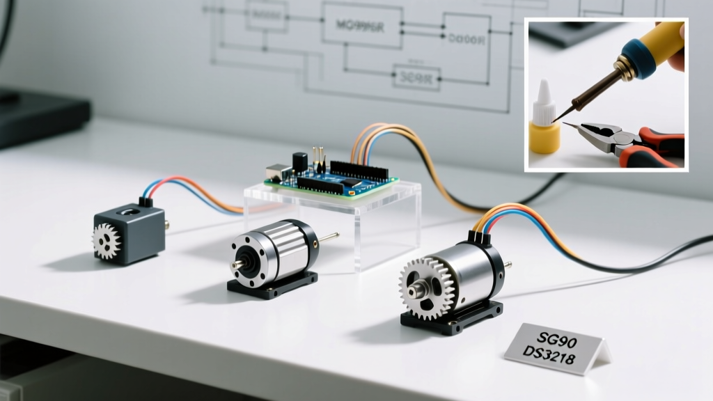
In this component comparison, we dissect the three most ubiquitous RC servos on the market: the TowerPro SG90, the TowerPro MG996R, and the DS3218MG (270-degree variant). We will explore the exact code required to drive each, the electrical failure modes you must engineer around, and when to abandon the Arduino's native timers in favor of I2C PWM drivers.
Component Comparison Matrix (2026 Market Data)
| Specification | TowerPro SG90 | TowerPro MG996R | DS3218MG (270°) |
|---|---|---|---|
| Stall Torque | 1.8 kg-cm | 13 kg-cm | 20 kg-cm |
| Gear Material | Delrin/Plastic | Brass/Steel | CNC Aluminum/Steel |
| Stall Current (5V) | ~700 mA | ~2.5 A | ~3.0 A |
| Rotation Range | 180° | 180° | 270° |
| Avg Price (2026) | $2.50 | $8.50 | $14.00 |
Baseline Code for Servo Arduino: The SG90 Micro
The SG90 is the standard starter servo. Its low stall current (700mA) means you can technically power a single unit directly from the Arduino Uno's 5V pin, though this is discouraged for motor-heavy circuits due to USB current limits (typically 500mA). The SG90 responds to standard PWM pulses ranging from 500 to 2400 microseconds.
According to the official Arduino Servo library documentation, the default attach() parameters assume a 544 to 2400 microsecond range. However, bench testing the SG90 reveals that it often fails to reach its full 180-degree mechanical travel unless you explicitly define the minimum pulse width to 500us.
#include <Servo.h>

Servo sg90Micro;
const int servoPin = 9;

void setup() {
  // Explicitly define min/max pulse widths for full SG90 travel
  sg90Micro.attach(servoPin, 500, 2400);
}

void loop() {
  sg90Micro.write(0);   // Full counter-clockwise
  delay(1500);
  sg90Micro.write(180); // Full clockwise
  delay(1500);
}
Edge Case Warning: The SG90's plastic gears are highly susceptible to stripping if the servo is commanded to move into a physical hard stop. Always leave a 5-degree software buffer (e.g., mapping your output to 5°–175°) if the servo is installed in a tight mechanical linkage.
Scaling Up: MG996R Power and Code Adjustments
The MG996R is the workhorse of DIY robotic arms and RC tank treads. While the code to drive the MG996R is identical to the SG90, the hardware interface is where 90% of beginners fail. The MG996R can draw up to 2.5 Amps under stall conditions.
The Brownout Failure Mode
If you wire the MG996R's VCC pin to the Arduino's 5V rail and command it to move under load, the sudden current spike will cause a voltage drop across the USB cable or onboard linear regulator. When the ATmega328P's voltage drops below its Brown-Out Detection (BOD) threshold (typically 4.3V), the microcontroller will instantly reset. You will see the Arduino's onboard LED flicker, and the servo will jitter violently in a continuous reboot loop.
The Fix: You must use an external 5V 3A (or higher) buck converter or Battery Eliminator Circuit (BEC). Wire the external 5V to the servo's VCC, and crucially, tie the external ground to the Arduino's GND. Without a common ground reference, the Arduino's PWM signal will float, causing erratic servo behavior.
Signal Wire Best Practices
The MG996R's high-current motor generates significant Electromagnetic Interference (EMI). If your PWM signal wire runs parallel to the power wires for more than 12 inches, the EMI can induce false pulses, resulting in position drift. Use twisted-pair wiring for the signal and ground lines, or add a 100µF electrolytic capacitor directly across the servo's VCC and GND pins at the motor end to smooth out transient voltage spikes.
High-Torque & Wide-Angle: DS3218MG 270-Degree Mapping
The DS3218MG is a premium, large-frame servo offering 20 kg-cm of torque. While standard 180-degree versions exist, the 270-degree variant is highly sought after for robotic joints and heavy-duty steering mechanisms. This is where the standard servo.write(angle) function fails you.
The Arduino Servo.h library's write() function inherently maps 0-180 to the default microsecond range. If you send write(270) to a 270-degree servo, the library caps it at 180, limiting your mechanical range. To unlock the full 270 degrees, you must bypass the degree abstraction and use writeMicroseconds().
Custom Microsecond Mapping for 270° Sweep
Most 270-degree digital servos expect a pulse width ranging from 500us (0 degrees) to 2500us (270 degrees). We use the Arduino map() function to translate our desired angle into the correct microsecond pulse.
#include <Servo.h>

Servo ds3218Heavy;
const int servoPin = 10;
int targetAngle = 270; // Desired angle (0 to 270)

void setup() {
  // Attach without overriding default min/max, we will handle it in loop
  ds3218Heavy.attach(servoPin);
}

void loop() {
  // Map 0-270 degrees to 500-2500 microseconds
  int pulseWidth = map(targetAngle, 0, 270, 500, 2500);

  // Constrain to prevent sending out-of-bounds pulses
  pulseWidth = constrain(pulseWidth, 500, 2500);

  ds3218Heavy.writeMicroseconds(pulseWidth);
  delay(2000);

  // Toggle for demonstration
  targetAngle = (targetAngle == 270) ? 0 : 270;
}
As noted in Pololu's comprehensive RC servo guide, digital servos like the DS3218MG hold their position with much higher force than analog servos. If your mechanical linkage binds, the servo will continue to draw stall current (3.0A) trying to reach the target pulse width, potentially melting the wiring harness or burning out the internal H-bridge. Always implement software timeouts or current-sensing feedback in heavy-load applications.
When to Ditch Servo.h for the PCA9685 Driver
The native Arduino Servo.h library relies on hardware timer interrupts to generate the 50Hz PWM signal. On an ATmega328P (Uno/Nano), this monopolizes Timer1. If your project requires IR remote decoding, ultrasonic sensor ping timing, or SoftwareSerial communication, you will encounter severe interrupt conflicts resulting in servo jitter and dropped serial packets.
Furthermore, if you are building a hexapod or a 6-DOF robotic arm using multiple MG996R or DS3218 servos, the Arduino's 5V linear regulator and native pins cannot handle the routing or the current.
The I2C PWM Solution
The PCA9685 16-Channel PWM Driver offloads signal generation to a dedicated I2C chip. As detailed in Adafruit's PCA9685 documentation, this board handles the precise timing for up to 16 servos independently of the Arduino's main CPU, freeing up your timers for complex kinematics calculations.
Using the Adafruit PWM library, the code shifts from angle-based writes to raw 12-bit tick values (0-4095), providing vastly superior resolution for smooth, slow-pan camera gimbals.
Summary Checklist for 2026 Servo Integration
- SG90 (Micro): Use
attach(pin, 500, 2400). Keep loads under 1kg-cm. Safe for single-unit Arduino 5V rail testing. - MG996R (Standard): Standard
write()code, but mandatory external 5V 3A BEC. Tie grounds. Add 100µF decoupling caps. - DS3218MG (270°): Requires
map()andwriteMicroseconds()to achieve full rotation. Watch for 3A stall current spikes. - Multi-Servo Setups: Abandon
Servo.hand migrate to an I2C PCA9685 driver to prevent timer interrupt collisions and CPU jitter.
By matching your code architecture to the specific electrical and mechanical profile of your chosen servo, you eliminate the most common points of failure in embedded robotics and ensure long-term reliability in your peripheral interfacing.