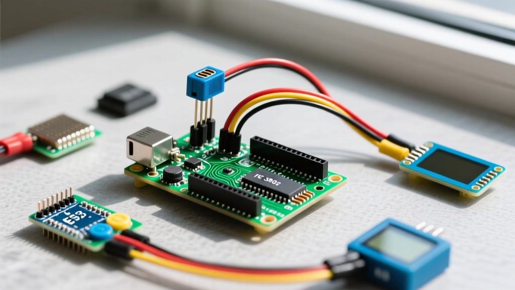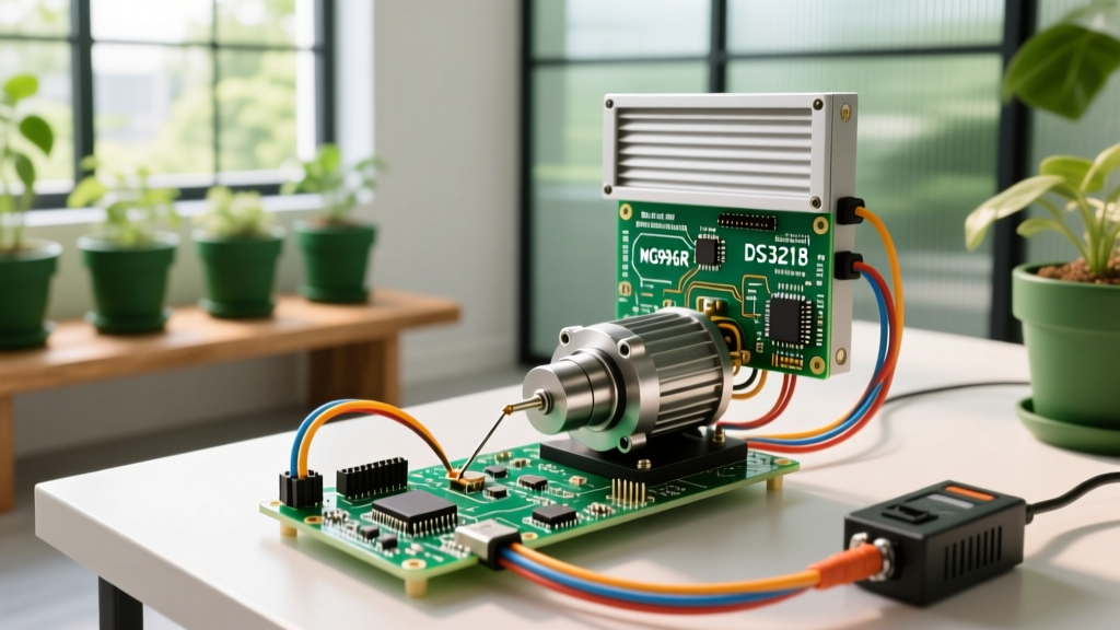

Real-World Ag-Tech: Automating Greenhouse Ventilation
In the rapidly evolving landscape of 2026 agricultural technology, automated climate control is no longer limited to massive commercial operations. Hobbyist and mid-scale growers are increasingly turning to microcontroller-based automation to manage greenhouse environments. One of the most critical, yet mechanically demanding, applications is the automation of ventilation louvers. When designing a robust servo Arduino system for outdoor or semi-outdoor louver control, the standard hobbyist tutorials fall dangerously short. Real-world wind loads, humidity, and high stall currents require a rigorous engineering approach to prevent gear stripping, microcontroller brownouts, and catastrophic linkage failure.
This guide bypasses the basic 'sweep' tutorials and dives deep into the electrical, mechanical, and software architecture required to build a heavy-duty louver actuator using high-torque digital servos and modern ESP32-based Arduino boards.
The 5V Pin Trap: Why Your Microcontroller Keeps Resetting
Critical Engineering Warning: Never power a high-torque metal-gear servo directly from the Arduino 5V or 3.3V pins. Doing so is the number one cause of erratic PWM signaling and permanent voltage regulator damage in DIY actuator projects.
A standard Arduino Nano ESP32 or Uno R4 features an onboard voltage regulator designed to supply roughly 500mA to 1A of continuous current, assuming adequate heat dissipation. However, a high-torque servo like the DS3218 can draw upwards of 2.8A during stall conditions (when the louver is stuck or fighting high wind resistance). When the servo demands this current, the voltage on the microcontroller's 5V rail sags below the brownout detection threshold (typically around 2.7V to 3.3V for the ESP32). The resulting microcontroller reset causes the PWM signal to drop to zero, which many servos interpret as a command to snap back to 0 degrees, violently slamming the louver shut and stripping the internal gears.
Component Selection Matrix: Analog vs. Digital High-Torque Servos
Selecting the right actuator requires balancing stall torque, current draw, and holding accuracy. According to fundamental servo control principles, digital servos offer higher holding torque and faster response times due to higher frequency PWM driving the internal DC motor, making them vastly superior for outdoor wind-load applications.
| Servo Model | Type | Stall Torque (6V) | Stall Current | 2026 Avg. Price | Best Application |
|---|---|---|---|---|---|
| TowerPro MG996R | Analog | 13 kg-cm | 2.0A | $7.50 | Light indoor louvers, low wind areas |
| DS3218 (20kg) | Digital | 20 kg-cm | 2.8A | $14.00 | Outdoor louvers, high wind resistance |
| FEETECH SCS15 | Serial Bus | 15 kg-cm | 1.5A | $16.50 | Multi-louver daisy-chaining (TTL serial) |
For a standard 2-foot by 1-foot polycarbonate louver exposed to 20 MPH winds, the calculated hinge torque requirement is approximately 6.5 kg-cm. Applying a standard safety factor of 3x for gust loads and mechanical friction, you need a minimum of 19.5 kg-cm. The DS3218 digital servo is the optimal choice here, providing 20 kg-cm of torque while maintaining a relatively affordable price point.
Power Architecture: Designing a Brownout-Proof Supply
To reliably drive a DS3218 alongside an Arduino Nano ESP32, you must isolate the high-current servo rail from the logic rail. We utilize a step-down buck converter to efficiently drop a 12V lead-acid or LiFePO4 battery down to a stable 6V for the servo, while a separate linear regulator handles the 3.3V/5V logic for the microcontroller.
Step-by-Step Power Wiring
- Primary Step-Down: Connect your 12V battery to the input of an LM2596 Buck Converter module. Adjust the potentiometer on the module until the output reads exactly 5.8V (the upper safe limit for most 6V-rated servos, maximizing torque without frying the internal PCB).
- Capacitor Bank: Solder a 1000µF 16V Low-ESR electrolytic capacitor directly across the VCC and GND wires at the servo connector. This acts as a localized energy reservoir, absorbing the instantaneous 2.8A current spike when the motor starts, preventing voltage sag on the main power lines.
- Common Ground: The ground (GND) of the battery, the buck converter, the servo, and the Arduino ESP32 must be tied together. Without a common ground reference, the PWM signal from the Arduino will be unreadable by the servo's internal comparator.
- Signal Isolation: Connect the Arduino PWM pin to the servo signal wire. For extreme electrical noise environments, place a 100Ω resistor in series with the signal wire and a 4.7kΩ pull-down resistor between the signal wire and GND to prevent ghost movements during microcontroller boot-up.
Code Implementation: Smooth Sweeping with ESP32 LEDC
While the standard Arduino Servo Library is excellent for AVR-based boards, the ESP32 architecture utilizes the LEDC (LED Control) hardware peripheral to generate highly stable PWM signals. Using hardware-backed PWM ensures that even if your code experiences a momentary delay (e.g., writing to an SD card or fetching Wi-Fi weather data), the PWM pulse train to the servo remains perfectly timed at 50Hz (20ms period).
// ESP32 Native LEDC Servo Control for DS3218
const int servoPin = 18;
const int pwmFreq = 50; // 50Hz standard for RC servos
const int pwmResolution = 16; // 16-bit resolution (0-65535)

// DS3218 Pulse Width Mapping (approx 500us to 2500us)
const int minPulse = 1638; // (500 / 20000) * 65535
const int maxPulse = 8192; // (2500 / 20000) * 65535

void setup() {
  Serial.begin(115200);
  ledcAttach(servoPin, pwmFreq, pwmResolution);

  // Soft-start: Move to center position slowly to prevent gear shock
  moveToAngle(90);
}

void loop() {
  // Example: Open louver fully at 2 PM, close at 6 PM
  // Insert real-time clock (RTC) or NTP logic here

  if (Serial.available()) {
    int targetAngle = Serial.parseInt();
    if (targetAngle >= 0 && targetAngle <= 180) {
      moveToAngle(targetAngle);
    }
  }
}

void moveToAngle(int angle) {
  int dutyCycle = map(angle, 0, 180, minPulse, maxPulse);
  ledcWrite(servoPin, dutyCycle);
  delay(500); // Allow time for mechanical transit
}
Mechanical Linkage and Wind Load Mitigation
Electrical perfection means nothing if the mechanical linkage fails. High-torque servos can easily snap 3D-printed PLA horns. For outdoor greenhouse louvers, you must upgrade the mechanical interface.
- Servo Horn: Discard the plastic cross-horns. Use the included aluminum 25-tooth spline horn that comes with the DS3218.
- Pushrod Material: Use 3mm stainless steel pushrods with M3 steel ball-link connectors. Avoid zip-ties or bent paperclips, which introduce mechanical slop (backlash), causing the servo to 'hunt' and jitter as it tries to find its center position.
- Environmental Sealing: Servos are not waterproof. Build a small PETG or ABS enclosure for the servo, utilizing a silicone gasket around the output shaft. Apply marine-grade dielectric grease to the external metal linkage joints to prevent rust-induced friction spikes that lead to over-current stalls.
Troubleshooting Real-World Glitches (FAQ)
Why is my servo jittering violently when holding position?
Jitter is almost always caused by electrical noise on the PWM signal line or an inadequate power supply ground. If you are using long wires (over 12 inches) between the Arduino and the servo, the signal wire acts as an antenna for EMI generated by nearby AC water pumps or grow lights. Fix: Use shielded cable for the PWM signal, connect the shield to GND at the Arduino end only, and ensure the 1000µF capacitor is placed as close to the servo connector as physically possible.
The servo hums but won't move the louver. Is it broken?
Not necessarily. This is a 'stall' condition. The static friction of the louver hinges, combined with wind pressure, exceeds the servo's 20 kg-cm breakaway torque. Fix: Lubricate the louver pivot points with white lithium grease. If the problem persists, increase the mechanical advantage by moving the ball-link connection closer to the servo horn's center (reducing the moment arm), or upgrade to a linear actuator for direct-push applications.
Can I power three DS3218 servos from one LM2596 buck converter?
Yes, but with caveats. The LM2596 is rated for 3A continuous. Three DS3218 servos moving simultaneously could draw up to 8.4A in a worst-case stall scenario, causing the buck converter to overheat and trigger its internal thermal shutdown. Fix: If actuating multiple louvers, stagger their movement in software (move Servo A, wait 1 second, move Servo B) or upgrade to a higher-capacity synchronous buck converter like the MP1584EN, which can handle 8A continuous with proper heatsinking.