
Navigating the Sound Sensor Arduino Ecosystem in 2026
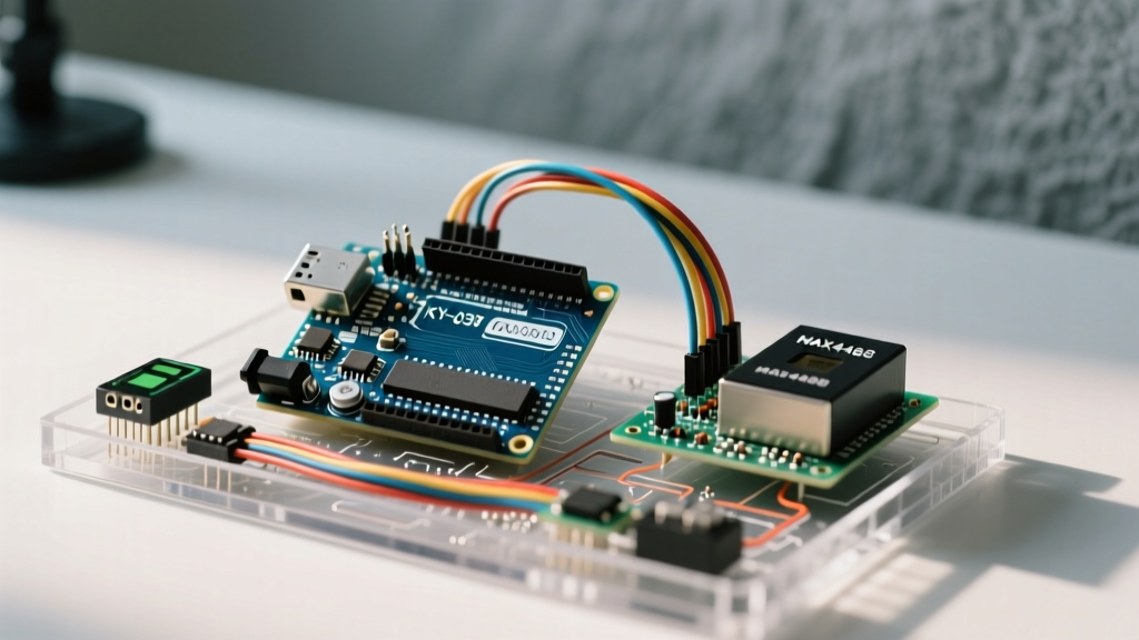
Integrating audio reactivity into microcontroller projects remains a cornerstone of interactive electronics. Whether you are building a voice-activated relay, an LED music visualizer, or a localized noise pollution monitor, selecting the right hardware and writing optimized firmware is critical. When searching for a sound sensor Arduino solution, makers typically encounter two vastly different modules: the digital KY-038 and the analog MAX4466. While both are colloquially called 'sound sensors,' their internal architectures, wiring requirements, and code implementations are entirely distinct.
This guide bypasses generic overviews to provide a deep-dive, engineering-grade breakdown of how to wire, calibrate, and code both modules. We will explore the LM393 comparator mechanics of the KY-038 for interrupt-driven transient detection, and the DC-biased analog output of the MAX4466 for true audio level metering.
Hardware Comparison Matrix: Choosing the Right Module
Before wiring a single jumper, you must match the sensor to your application's signal processing requirements. The table below compares the three most common modules available in the 2026 maker market.
| Module | Core IC | Output Type | Best Use Case | Avg. Price (2026) |
|---|---|---|---|---|
| KY-038 | LM393 Comparator | Digital (HIGH/LOW) & Raw Analog | Clap switches, knock detectors, basic noise triggers | $1.50 - $3.00 |
| MAX4466 | MAX4466 Op-Amp | Analog (DC Biased) | VU meters, audio visualizers, volume tracking | $6.95 - $9.50 |
| MAX9814 | MAX9814 Auto-Gain | Analog (DC Biased) | Speech recognition, quiet environment monitoring | $12.00 - $15.00 |
Part 1: KY-038 Digital Trigger Wiring & Interrupt Code
The KY-038 is essentially an electret microphone capsule paired with an LM393 voltage comparator. The comparator takes the raw analog microphone signal and compares it against a reference voltage set by the onboard trimpot (potentiometer). When the audio transient exceeds this threshold, the digital output pin (DO) pulls LOW.
Wiring the KY-038 for Transient Detection
- VCC: Connect to 5V (Do not use 3.3V; the LM393 requires a higher voltage headroom to properly drive the output stage and power the onboard electret bias).
- GND: Connect to Arduino GND.
- DO (Digital Out): Connect to Pin 2 on the Arduino Uno/Nano. We specifically choose Pin 2 because it supports hardware external interrupts (INT0).
- AO (Analog Out): Leave unconnected for pure digital trigger applications.
Calibrating the Trimpot
The blue trimpot on the KY-038 dictates the trigger threshold. Turn it clockwise to increase sensitivity (lower threshold), and counter-clockwise to decrease it. Pro-Tip: Monitor the onboard LED labeled 'L1'. It will illuminate when the output is LOW (triggered). Adjust the pot until the LED flickers only on sharp, intentional transients like a hand clap, ignoring ambient room noise.
The Firmware: Why Polling Fails and Interrupts Succeed
A common beginner mistake is using digitalRead() inside the loop() to check the KY-038. Audio transients (like a clap or a knuckle knock) last only 10 to 50 milliseconds. If your loop is busy updating an LCD or driving a servo, you will entirely miss the pulse. The correct architectural approach is using an Interrupt Service Routine (ISR).
// KY-038 Interrupt-Driven Clap Detector
const int soundDigitalPin = 2; // INT0 on Arduino Uno/Nano
volatile bool soundDetected = false;
unsigned long lastTriggerTime = 0;
const unsigned long debounceDelay = 150; // ms

void setup() {
  Serial.begin(115200);
  pinMode(soundDigitalPin, INPUT);
  // Attach interrupt on FALLING edge (LM393 pulls DO to GND when triggered)
  attachInterrupt(digitalPinToInterrupt(soundDigitalPin), soundISR, FALLING);
}

void soundISR() {
  soundDetected = true;
}

void loop() {
  if (soundDetected) {
    unsigned long currentTime = millis();
    // Software debouncing to prevent mechanical echo triggers
    if (currentTime - lastTriggerTime > debounceDelay) {
      Serial.println('Transient Detected! Executing payload...');
      lastTriggerTime = currentTime;
    }
    soundDetected = false; // Reset the flag
  }

  // Your main non-blocking code goes here
}
Engineering Note: Notice theFALLINGedge parameter inattachInterrupt(). The LM393 features an open-collector output. It cannot drive a pin HIGH; it can only pull it to GND. The Arduino's internal pull-up resistor (or an external 10kΩ resistor) keeps the pin HIGH until the comparator triggers, pulling it LOW.
Part 2: MAX4466 Analog Audio Metering & Peak-to-Peak Math
If your project requires measuring the actual volume or frequency content of audio, the KY-038 is insufficient. The MAX4466 breakout board features a specialized op-amp designed specifically for electret microphones, offering a clean, amplified analog signal with a fixed DC bias.
Understanding the VCC/2 DC Bias
Microphones output AC signals (oscillating positive and negative). However, the Arduino's ADC (Analog-to-Digital Converter) can only read positive voltages between 0V and 5V. To solve this, the MAX4466 circuit offsets the audio signal by exactly half the supply voltage (VCC/2). If you power the MAX4466 with 5V, the resting output on the OUT pin will be 2.5V (which reads as ~512 on the 10-bit ADC). Audio waves will oscillate above and below this 512 baseline.
Wiring the MAX4466
- VCC: Connect to 5V. (Ensure your 5V rail is clean; switching regulators on cheap Arduino clones will inject high-frequency noise into the audio signal).
- GND: Connect to Arduino GND.
- OUT: Connect to Pin A0.
The Firmware: Calculating Peak-to-Peak Voltage
To measure volume, we do not need complex Fast Fourier Transforms (FFT) unless we are analyzing specific frequencies. For general volume metering, calculating the Peak-to-Peak (P-P) amplitude over a short sampling window is highly efficient. According to the Adafruit Microphone Amplifier Guide, sampling for 50ms provides an excellent balance for capturing audio envelopes without blocking the main loop for too long.
// MAX4466 Peak-to-Peak Volume Meter
const int micPin = A0;
const int sampleWindow = 50; // Sample window in milliseconds

void setup() {
  Serial.begin(115200);
}

void loop() {
  unsigned long startMillis = millis();
  unsigned int peakToPeak = 0;
  unsigned int signalMax = 0;
  unsigned int signalMin = 1024;
  unsigned int sample;

  // Collect samples for the duration of the window
  while (millis() - startMillis < sampleWindow) {
    sample = analogRead(micPin);
    if (sample < 1024) { // Toss out spurious readings
      if (sample > signalMax) {
        signalMax = sample; // Save just the max level
      } else if (sample < signalMin) {
        signalMin = sample; // Save just the min level
      }
    }
  }

  // Calculate the delta (Peak-to-Peak)
  peakToPeak = signalMax - signalMin;

  // Convert to Volts (Assuming 5V reference on 10-bit ADC)
  // Note: We do NOT subtract the 512 DC bias here because
  // subtracting Min from Max naturally cancels out the offset.
  double volts = (peakToPeak * 5.0) / 1024.0;

  Serial.print('Audio P-P Voltage: ');
  Serial.println(volts);
}
Advanced Troubleshooting & Failure Modes
When working with audio peripherals, environmental and electrical noise frequently derail projects. Below is a diagnostic framework for common sound sensor Arduino integration failures.
1. The 50Hz/60Hz Mains Hum Problem
Symptom: Your MAX4466 readings fluctuate rhythmically even in a 'quiet' room, or your KY-038 triggers randomly at night.
Root Cause: Electromagnetic interference (EMI) from AC wall wiring or unshielded LED drivers. The electret capsule acts as an antenna.
Solution: Keep sensor wires under 10cm in length. If longer runs are required, use shielded twisted-pair (STP) cable with the shield tied to GND at the Arduino end only. Additionally, place a 100nF ceramic decoupling capacitor directly across the VCC and GND pins on the sensor module.
2. ADC Saturation and Clipping
Symptom: Loud sounds result in lower-than-expected voltage readings, or the waveform appears 'squared off' in serial plotter.
Root Cause: The MAX4466 gain is too high, pushing the audio peaks past the 5V rail or below the 0V GND rail. The Arduino analogRead() function simply caps at 1023 and 0, destroying the waveform data.
Solution: If using the adjustable MAX4466 breakout, use a small flathead screwdriver to turn the gain trimpot counter-clockwise. Target a resting P-P voltage of ~0.5V in a normal speaking environment to leave adequate headroom for loud transients.
3. Mechanical Vibration Coupling
Symptom: The sensor triggers or spikes when the enclosure is bumped, even without acoustic noise.
Root Cause: Electret microphones are physically sensitive to structure-borne vibrations. If you mount the KY-038 directly to a chassis with vibrating DC motors or servos, it will register mechanical shocks as audio.
Solution: Isolate the sensor using foam tape or a rubber grommet between the module's PCB and the project enclosure. Never hot-glue the microphone capsule directly to a rigid motor mount.
Summary
Successful audio integration relies on choosing the correct topology for your goal. Use the KY-038 with hardware interrupts for low-latency, binary acoustic triggers. Deploy the MAX4466 with Peak-to-Peak sampling windows for smooth, accurate volume metering. By respecting the analog nuances of DC biasing, open-collector outputs, and EMI shielding, your 2026 microcontroller audio projects will achieve professional-grade reliability.