
Introduction to the L298N Dual H-Bridge
Interfacing high-current DC motors directly with a microcontroller is a guaranteed way to destroy your board. Microcontroller GPIO pins typically max out at 20mA to 40mA, while even small hobby motors require 500mA to 2A under load. This is where a dedicated motor controller becomes mandatory. For beginners, the L298N motor driver Arduino setup remains the most ubiquitous entry point into robotics and motor control.
The L298N is a dual full-bridge driver based on Bipolar Junction Transistor (BJT) technology. While modern MOSFET-based drivers have largely surpassed it in efficiency, the L298N's ruggedness, forgiving logic levels, and extremely low market price (typically $2.50 to $4.50 for generic modules in 2026) make it the standard for educational robotics and beginner prototyping.
Module Pinout and Electrical Specifications
Before wiring, you must understand the physical and electrical limits of the IC. According to the STMicroelectronics L298N Datasheet, the IC can handle up to 35V and 2A per channel. However, continuous current without a heatsink should be limited to roughly 1A to prevent thermal shutdown.
| Pin / Terminal | Function | Specifications & Notes |
|---|---|---|
| 12V / VCC | Motor Power Supply (Vs) | Accepts 5V to 35V DC. Do not exceed 35V. |
| GND | Common Ground | Must be shared with Arduino GND and power supply. |
| 5V Output | Onboard 7805 Regulator | Provides 5V logic power if jumper is installed and Vs < 12V. |
| ENA / ENB | Enable Pins (PWM) | Controls speed via PWM. HIGH = Enabled. Remove default jumper for MCU control. |
| IN1, IN2 | Logic Inputs (Motor A) | Digital 5V logic to set direction (Forward/Reverse/Brake). |
| IN3, IN4 | Logic Inputs (Motor B) | Digital 5V logic to set direction (Forward/Reverse/Brake). |
| OUT1, OUT2 | Motor A Output | Connects to DC Motor A terminals. |
| OUT3, OUT4 | Motor B Output | Connects to DC Motor B terminals. |
Essential Hardware and 2026 Pricing
To replicate this tutorial, you will need the following components. Prices reflect average 2026 market rates from major electronics distributors:
- L298N Module: Generic red or black dual H-bridge modules ($2.50 - $4.50).
- Microcontroller: Arduino Uno R3 or R4 Minima ($22.00 - $28.00).
- Power Supply: 2S LiPo (7.4V) or 3S LiPo (11.1V) battery pack, or a 9V/12V DC wall adapter ($10.00 - $15.00).
- Motors: Standard TT gearmotors (3V-6V) with yellow chassis ($3.00/pair).
- Wiring: 22 AWG stranded silicone wire and male-to-female jumper wires.
Step-by-Step Wiring Guide
Proper wiring is critical. A missed common ground is the number one reason beginners experience erratic motor behavior or fried microcontrollers.
1. Power and Ground Connections
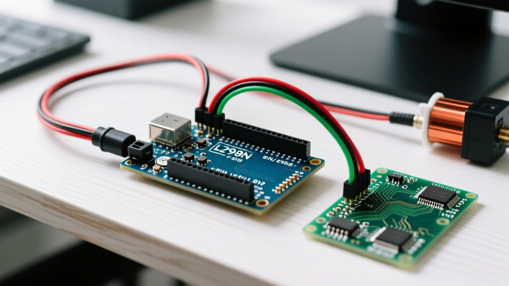
Connect your external battery pack's positive terminal to the 12V (VCC) screw terminal on the L298N. Connect the battery's negative terminal to the GND screw terminal. Crucial: Run a secondary wire from the L298N GND terminal to one of the Arduino's GND pins. The logic circuits require a shared ground reference to read the 5V GPIO signals correctly.
⚠️ Critical 12V Jumper Warning:Locate the small jumper cap next to the 5V terminal. If your motor power supply is 12V or less, leave the jumper ON to power the Arduino via the 5V pin. If your power supply is greater than 12V (e.g., a 14.4V drill battery), you MUST REMOVE this jumper. Leaving it on will force the onboard 7805 linear regulator to dissipate excess voltage as heat, rapidly leading to thermal failure and permanent module damage.
2. Logic and PWM Connections
Remove the factory-installed jumpers on ENA and ENB. We need the Arduino to control speed via Pulse Width Modulation (PWM). Wire the modules as follows:
- ENA to Arduino Pin 9 (PWM capable)
- IN1 to Arduino Pin 8
- IN2 to Arduino Pin 7
- ENB to Arduino Pin 3 (PWM capable)
- IN3 to Arduino Pin 5
- IN4 to Arduino Pin 4
3. Motor Outputs
Connect Motor A to OUT1 and OUT2. Connect Motor B to OUT3 and OUT4. DC motors are non-polarized, so the exact order doesn't matter initially; you can simply swap the wires later in software if a motor spins backward.
Arduino Code: Controlling Direction and Speed
The logic for an H-bridge is straightforward: setting IN1 HIGH and IN2 LOW drives the motor forward. Reversing them drives it backward. Setting both LOW coasts the motor, while setting both HIGH applies dynamic braking. Speed is dictated by the duty cycle of the PWM signal on the Enable pin.
For deeper context on motor physics and PWM theory, refer to the Arduino Official Motor Documentation.
// L298N Motor Control Variables
const int ENA = 9;
const int IN1 = 8;
const int IN2 = 7;

void setup() {
  pinMode(ENA, OUTPUT);
  pinMode(IN1, OUTPUT);
  pinMode(IN2, OUTPUT);

  // Ensure motor is stopped on boot
  digitalWrite(IN1, LOW);
  digitalWrite(IN2, LOW);
}

void loop() {
  // 1. Drive Forward at 75% Speed
  setMotor(190, true);  // 190/255 ≈ 75%
  delay(2000);

  // 2. Hard Brake
  brakeMotor();
  delay(500);

  // 3. Drive Reverse at 50% Speed
  setMotor(127, false);
  delay(2000);

  // 4. Coast to Stop
  digitalWrite(IN1, LOW);
  digitalWrite(IN2, LOW);
  analogWrite(ENA, 0);
  delay(2000);
}

void setMotor(int speed, boolean isForward) {
  if (isForward) {
    digitalWrite(IN1, HIGH);
    digitalWrite(IN2, LOW);
  } else {
    digitalWrite(IN1, LOW);
    digitalWrite(IN2, HIGH);
  }
  analogWrite(ENA, speed);
}

void brakeMotor() {
  digitalWrite(IN1, HIGH);
  digitalWrite(IN2, HIGH);
  analogWrite(ENA, 255);
  delay(100); // Hold brake briefly
}
Real-World Troubleshooting and Failure Modes
Beginners frequently encounter specific edge cases when using the L298N. Here is how to diagnose and fix them:
Motor Hums but Fails to Spin
The Cause: The BJT topology of the L298N introduces a significant voltage drop of roughly 1.8V to 2.2V across the internal transistors. If you supply 5V to the VCC terminal to drive a 5V motor, the motor only receives ~3V. Under mechanical load, this voltage sags further, resulting in a stall.
The Fix: Always supply a voltage 2.5V higher than your motor's rated voltage. For standard 6V TT gearmotors, use an 8.4V or 9V battery pack.
Arduino Resets or Behaves Erratically During Motor Start
The Cause: DC motors generate massive Back-EMF (electromotive force) voltage spikes when starting, stopping, or changing direction. Furthermore, high inrush currents can cause the shared power rail to brown out the Arduino.
The Fix: Ensure your L298N module has flyback diodes installed (usually 1N4007 diodes arranged in an H-pattern on the board). If using a cheap clone module lacking these, solder Schottky diodes (like 1N5819) across the motor terminals. Additionally, power the Arduino from a separate 5V USB source rather than relying on the L298N's 5V output during heavy loads.
L298N vs. Modern Alternatives (2026 Comparison)
While the L298N is an excellent learning tool, its BJT design is highly inefficient compared to modern MOSFET drivers. If your project requires battery longevity or compact sizing, consider these alternatives:
| Driver IC | Topology | Max Continuous Current | Voltage Drop | Avg Price (2026) | Best Use Case |
|---|---|---|---|---|---|
| L298N | BJT | 2.0A | ~2.0V | $3.00 | Education, high-voltage (12V+) bench prototyping |
| TB6612FNG | MOSFET | 1.2A | ~0.5V | $6.50 | Mobile robots, battery-powered 6V platforms |
| DRV8833 | MOSFET | 1.5A | ~0.3V | $4.00 | Compact IoT devices, low-voltage efficiency (see TI DRV8833 Specs) |
Expert Takeaway: Stick with the L298N if you are driving 12V motors from a wall adapter or learning H-bridge logic. Upgrade to a TB6612FNG or DRV8833 the moment your project transitions to battery-powered mobile robotics, as the 2V dropout of the L298N will severely limit your runtime and torque.
Frequently Asked Questions
Can I use the L298N with a 3.3V microcontroller like the ESP32?
Yes, but with a caveat. The L298N requires a minimum logic HIGH voltage of 2.3V, which the ESP32 satisfies. However, for reliable switching at high PWM frequencies, the logic threshold ideally wants to be closer to 5V. If you experience jittery motor control, use a simple logic level shifter or optocoupler between the ESP32 and the IN pins.
Does the L298N support stepper motors?
Yes. Because it contains two independent H-bridges, it can perfectly drive a standard 4-wire bipolar stepper motor by energizing the coils in the correct sequence via your Arduino code.