
Beyond Basic Wiring: The Calibration Mindset
When searching for instructions on how to interface Arduino with an OLED display, the vast majority of tutorials stop at four jumper wires and a default library call. While this gets pixels on the screen, it completely ignores the physics of the I2C bus and the internal register architecture of the OLED controller. In 2026, as DIY sensor dashboards demand higher reliability and precision, treating your display as a simple 'plug-and-play' peripheral leads to ghosting, I2C bus lockups, and premature burn-in.
True display accuracy requires calibrating both the hardware bus integrity and the software display registers. Whether you are building a high-speed oscilloscope readout or a slow-updating environmental sensor hub, mastering these calibration techniques ensures your data is rendered with absolute fidelity.
Hardware Selection & I2C Bus Integrity
Before writing a single line of code, you must address the physical layer. The most common point of failure when interfacing microcontrollers with OLEDs is I2C bus capacitance and logic-level mismatch.
The Level-Shifting Imperative
Most standard Arduinos (like the Uno R3 or Mega 2560) operate at 5V logic. However, the SSD1306 and SH1106 OLED controllers are strictly 3.3V devices. While many makers connect 5V SDA/SCL lines directly to the OLED and it 'seems' to work, this relies on the controller's internal ESD protection diodes to clamp the voltage. Over time, this degrades the silicon, increases leakage current, and causes phantom pixels.
- The Professional Fix: Use a BSS138-based bidirectional level shifter (approx. $1.50). This cleanly translates 5V logic to 3.3V without signal edge degradation.
- The Native Alternative: Upgrade to a 3.3V native board like the Arduino Nano 33 IoT or the ESP32, eliminating the need for translation entirely.
Pull-Up Resistor Calibration
The I2C bus requires pull-up resistors to return the SDA and SCL lines to a HIGH state. According to the Arduino Official Wire Library Documentation, the internal pull-ups (approx. 20kΩ to 50kΩ) are far too weak for the capacitance introduced by OLED modules and jumper wires.
Expert Rule of Thumb: For standard 100kHz I2C, use 4.7kΩ pull-ups. If you are pushing the bus to 400kHz Fast Mode to increase display refresh rates, drop to 2.2kΩ pull-ups to sharpen the rising edges of the signal.
Module Comparison: Generic vs. Premium
| Module Type | Approx. Cost (2026) | I2C Pull-Ups | Voltage Regulator | Best Use Case |
|---|---|---|---|---|
| Generic HiLetgo SSD1306 (0.96") | $3.50 - $5.00 | Often missing or 10kΩ | Cheap AMS1117 (high dropout) | Prototyping, low-budget builds |
| Adafruit SSD1306 Breakout | $17.50 | Precision 4.7kΩ included | AP2112K-3.3 (low noise) | Production, high-accuracy dashboards |
| SH1106 1.3" I2C Module | $6.00 - $8.00 | Variable | Integrated LDO | Larger UI elements, lower pixel density |
Pinout & Wiring Matrix
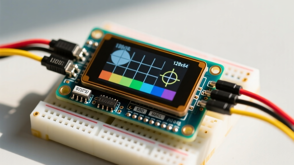
For a standard 128x64 I2C OLED, the wiring is straightforward, but the physical routing matters. Keep I2C traces under 30cm to avoid exceeding the 400pF bus capacitance limit defined by NXP standards.
| OLED Pin | Arduino Uno (ATmega328P) | Calibration & Routing Note |
|---|---|---|
| GND | GND | Ensure a star-ground topology to avoid ground loops with motors. |
| VCC | 3.3V or 5V | If using a generic board on 5V, ensure the onboard LDO doesn't overheat. |
| SCL | A5 (or dedicated SCL) | Route away from high-frequency PWM motor control wires. |
| SDA | A4 (or dedicated SDA) | Add 2.2kΩ pull-up to 3.3V if using a level shifter. |
Software Calibration: Tuning the SSD1306 Registers
Libraries like U8g2 and Adafruit_SSD1306 send a default initialization sequence. However, these defaults are optimized for maximum brightness in a retail display case, not for the crisp, high-contrast accuracy needed for sensor data. To achieve pixel-perfect accuracy, we must inject raw I2C commands to tune the controller's internal registers.
1. Contrast and Luminance Tuning (0x81)
The default contrast is often set to 0x7F or 0xFF. On indoor dashboards, maximum contrast causes 'blooming' where white pixels bleed into adjacent black pixels, ruining text legibility. Setting the contrast register (0x81) to 0xCF (207) provides the sharpest edge definition without blooming.
2. Pre-Charge Period (0xD9)
This register controls how long the OLED pixels are charged and discharged. If you notice 'ghosting' or trailing artifacts when updating fast-moving graphs, the pre-charge period is likely too slow. Changing the default 0x22 to 0xF1 drastically reduces ghosting by aggressively discharging the OLED capacitors between frames.
3. VCOMH Deselect Level (0xDB)
This setting dictates the black level of the display. A poorly calibrated VCOMH level results in dark gray pixels instead of true black, reducing the effective contrast ratio. Setting this to 0x40 ensures the deepest possible blacks, which is critical for saving power on battery-operated sensor nodes.
Calibration Code Implementation
Below is an implementation showing how to override default library settings with calibrated hex commands immediately after initialization.
// SSD1306 Contrast & Bus Calibration for Arduino
#include <Wire.h>
#include <Adafruit_GFX.h>
#include <Adafruit_SSD1306.h>

#define SCREEN_WIDTH 128
#define SCREEN_HEIGHT 64
#define OLED_I2C_ADDR 0x3C // Verify with I2C Scanner

Adafruit_SSD1306 display(SCREEN_WIDTH, SCREEN_HEIGHT, &Wire, -1);

void calibrateOLED() {
  Wire.beginTransmission(OLED_I2C_ADDR);
  Wire.write(0x00); // Co=0, D/C#=0 (Command Mode)

  // 1. Set Contrast to 207 (Crisp indoor readability, no blooming)
  Wire.write(0x81); Wire.write(0xCF);

  // 2. Pre-charge period (0xF1 reduces ghosting on fast graph updates)
  Wire.write(0xD9); Wire.write(0xF1);

  // 3. VCOMH Deselect (0x40 for true black levels)
  Wire.write(0xDB); Wire.write(0x40);

  // 4. Clock Divider (0xF0 increases refresh rate to prevent camera flicker)
  Wire.write(0xD5); Wire.write(0xF0);

  Wire.endTransmission();
}

void setup() {
  Serial.begin(115200);
  if(!display.begin(SSD1306_SWITCHCAPVCC, OLED_I2C_ADDR)) {
    Serial.println(F('SSD1306 allocation failed'));
    for(;;); // Halt execution
  }

  calibrateOLED(); // Inject custom calibration registers

  display.clearDisplay();
  display.setTextSize(1);
  display.setTextColor(SSD1306_WHITE);
  display.setCursor(0,0);
  display.println('Calibration Complete.');
  display.display();
}

void loop() {
  // Sensor polling logic here
}
Mitigating Burn-In and Pixel Degradation
OLEDs generate light via organic compounds that degrade over time when subjected to high current. If your Arduino is displaying a static sensor threshold warning (e.g., a solid 'OVER TEMP' box) for weeks on end, those specific pixels will burn in, leaving a permanent ghost image.
Software Pixel Shifting
To maintain long-term accuracy and panel health, implement a software pixel shift. Every 60 seconds, shift the entire UI bounding box by 1 or 2 pixels on the X/Y axis. The Adafruit Learning System recommends this technique for static dashboards. Because the human eye cannot easily detect a 1-pixel shift on a 128x64 grid, the UI appears stationary while the physical OLED subpixels are given time to recover.
Dynamic Brightness Scaling
Integrate a simple LDR (Light Dependent Resistor) or an ambient light sensor like the TSL2591. Map the ambient lux to the OLED contrast register (0x81). In a dark room at night, drop the contrast to 0x40; in direct sunlight, push it to 0xFF. This not only saves battery life but mathematically extends the lifespan of the organic diodes by reducing unnecessary current draw.
Troubleshooting I2C Bus Lockups
A common failure mode when interfacing Arduinos with OLEDs is the microcontroller freezing during the display.display() buffer push. This happens when the I2C bus enters a deadlock state, usually caused by a voltage sag or a missed ACKnowledge (ACK) bit.
- Diagnose with a Logic Analyzer: Hook up a $10 USB logic analyzer to the SDA/SCL lines. If you see the SDA line stuck LOW while SCL is pulsing, the OLED controller has seized the bus.
- The Hardware Reset Trick: Many generic OLED boards do not break out the
RSTpin. If your module has it, wire it to a digital pin on the Arduino and pulse it LOW for 10ms, then HIGH, before re-initializing the I2C sequence. - Bus Extenders for Long Runs: If your sensor is housed in a weatherproof enclosure 2 meters away from the Arduino, standard I2C will fail. Use a PCA9615A I2C bus extender to convert the signal to a differential pair, allowing accurate OLED communication over multi-meter distances.
Final Thoughts on Display Fidelity
Understanding exactly how to interface Arduino with an OLED display is not just about making pixels light up; it is about ensuring the data you collect is represented with absolute visual accuracy. By properly managing I2C capacitance, utilizing level shifters, and diving into the SSD1306 register map to tune contrast, pre-charge, and refresh rates, you elevate your project from a fragile prototype to a robust, professional-grade instrument. Take the extra 30 minutes to calibrate your display hardware and software—the resulting clarity and reliability of your sensor dashboards will speak for themselves.