
The Ubiquitous 1602A: Why Your 16x2 LCD Display Arduino Project Fails
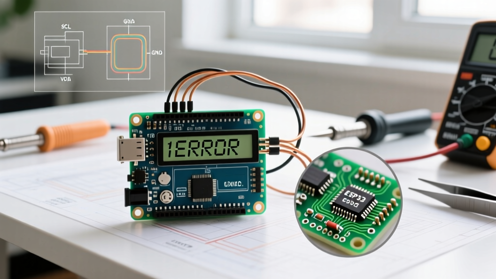
The Hitachi HD44780-based 1602A module remains a staple in electronics prototyping. However, integrating a 16x2 lcd display arduino setup is notoriously prone to silent failures. Whether you are staring at a blank blue screen, a row of solid white blocks, or garbled ASCII characters, the root cause almost always traces back to three domains: contrast voltage misalignment, I2C address mismatches, or power rail sagging.
In 2026, while bare parallel 1602A modules cost around $2.50 and pre-soldered I2C variants hover near $5.00, the underlying silicon and wiring physics remain unchanged. This guide bypasses generic advice and provides a component-level diagnostic framework to get your display operational.
Phase 1: Direct Parallel Wiring (HD44780) Troubleshooting
When wiring the 16-pin parallel interface directly to an Arduino Uno or Nano, you are typically using 4-bit mode to save digital I/O pins. If the backlight turns on but no text appears, the issue is rarely the Arduino code; it is almost always a hardware bias or control pin failure.
The Contrast Pin (V0) and the "Black Boxes" Syndrome
Pin 3 (V0) controls the liquid crystal bias voltage. This is the single most common point of failure for beginners.
- Solid Black/White Boxes on Row 1: The contrast is too high. The V0 pin is too close to GND (0V). You need to raise the voltage slightly.
- Completely Blank Screen: The contrast is too low. V0 is too close to VDD (5V).
Expert Fix: While tutorials recommend a 10kΩ trimpot, modern high-efficiency STN blue displays often require a V0 voltage between 0.2V and 0.8V. If you lack a potentiometer, a fixed 2.2kΩ resistor between V0 and GND will perfectly bias 90% of modern 16x2 modules without the mechanical drift associated with cheap trimpots.
The Floating RW Pin (Read/Write)
Pin 5 (RW) dictates whether the Arduino is writing data to the LCD or reading from it. Because the Arduino's digital pins are 5V tolerant but the HD44780 outputs 5V logic that can sometimes backfeed poorly isolated circuits, we almost exclusively use write-only mode.
Critical Rule: Pin 5 (RW) MUST be tied directly to GND. If left floating, the LCD controller may randomly enter read mode, locking up the internal data bus and resulting in a frozen or blank display.
Standard 4-Bit Mode Pinout Matrix
| LCD Pin | Symbol | Arduino Connection | Function & Troubleshooting Note |
|---|---|---|---|
| 1 | VSS | GND | Logic Ground. Must share common ground with Arduino. |
| 2 | VDD | 5V | Logic Power. Do not use 3.3V on standard 5V modules. |
| 3 | V0 | Wiper of 10k Pot | Contrast. Target 0.4V for standard blue/white displays. |
| 4 | RS | Digital Pin 12 | Register Select. HIGH = Data, LOW = Command. |
| 5 | RW | GND | Read/Write. MUST be grounded for write-only mode. |
| 6 | E | Digital Pin 11 | Enable. Triggers data latch on falling edge. |
| 11-14 | D4-D7 | Digital Pins 5,4,3,2 | Data lines. Ensure exact mapping in LiquidCrystal init. |
Phase 2: I2C Backpack Module (PCF8574) Diagnostics
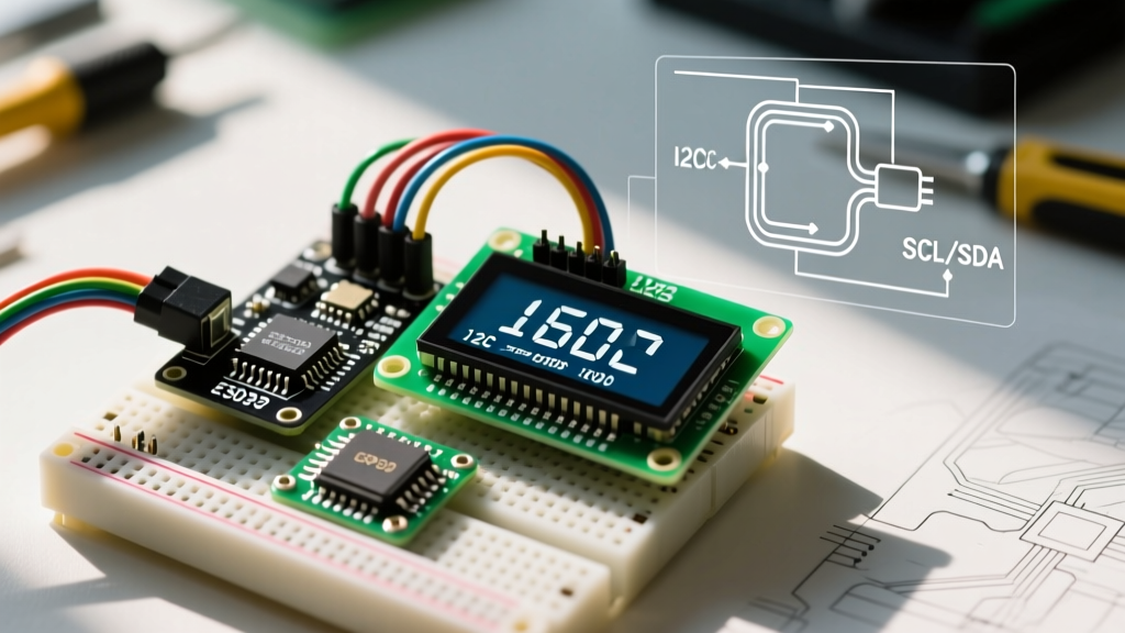
To save I/O pins, most modern makers use a 16-pin I2C backpack based on the PCF8574 or PCF8574A I/O expander. While wiring is reduced to four pins (VCC, GND, SDA, SCL), the abstraction layer introduces software-based failure modes.
The Address Conflict: 0x27 vs 0x3F
The most frequent reason an I2C LCD fails to initialize is an incorrect hexadecimal address in the constructor. The backpacks use jumper pads (A0, A1, A2) to configure the address, but the base address depends on the specific silicon chip used by the manufacturer.
- PCF8574 (NXP/TI standard): Base address is 0x20. With all jumpers open (high via pull-ups), the address shifts to 0x27.
- PCF8574A (NXP variant): Base address is 0x38. With all jumpers open, the address shifts to 0x3F.
According to the NXP PCF8574 Datasheet, the 'A' variant was designed specifically to allow multiple I/O expanders on the same bus without address collisions. If your LCD is unresponsive, run an I2C scanner sketch to verify if your module is responding at 0x27 or 0x3F.
Library Deprecation and the 2026 Standard
For years, the community relied on the `LiquidCrystal_I2C` library by Frank de Brabander. However, this library is largely unmaintained, hardcodes pin mappings that fail on newer clone backpacks, and lacks robust error handling.
The definitive standard for HD44780 I2C troubleshooting today is the hd44780 Library by Bill Perry. Unlike legacy libraries, the `hd44780` library features an auto-discovery engine that scans the I2C bus, identifies the backpack's internal pin mapping, and configures the display automatically. If your wiring is correct but the screen remains blank, migrating to the `hd44780_I2Cexp` class will resolve 80% of software-side mapping errors.
Phase 3: Power Delivery and Thermal Throttling
If your 16x2 lcd display arduino setup works perfectly on a desk but fails when integrated into a chassis or powered by a battery, you are likely experiencing power rail sagging.
Backlight Current Draw and Voltage Drop
The LED backlight on a standard 1602A module draws between 80mA and 120mA. When powered via the Arduino's 5V pin, this current is routed through the board's onboard linear regulator (often an NCP1117-5.0). If you are also powering sensors, relays, or servos, the regulator will hit its thermal limit (usually around 800mA total draw) and initiate thermal shutdown, causing the LCD to flicker or reset.
Hardware Solution: Never power the LCD backlight directly from the Arduino 5V pin in high-draw projects. Use a dedicated 5V buck converter (like an LM2596 module, costing ~$1.50) to supply the LCD VDD and Backlight Anode (Pin 15) directly from your main power source, ensuring you tie the grounds together.
Ghosting and Bus Capacitance
If characters appear faint, "ghosted," or shift positions randomly, the I2C bus is suffering from high capacitance. I2C is not designed for long cable runs. If your SDA/SCL wires exceed 30cm, the signal edges degrade, causing the PCF8574 to misinterpret bits.
- Keep I2C wires under 1 meter.
- Use twisted pair cables for SDA and SCL.
- Install 4.7kΩ pull-up resistors on both SDA and SCL lines if the backpack lacks them.
- Place a 100nF ceramic decoupling capacitor directly across the LCD's VDD and VSS pins to filter high-frequency noise.
Quick Diagnostic Matrix
Use this rapid-reference table to isolate your specific failure mode based on visual symptoms.
| Visual Symptom | Probable Root Cause | Actionable Fix |
|---|---|---|
| Blank screen, backlight ON | V0 voltage too high (near 5V) or RS/E pins swapped. | Adjust V0 trimpot to ~0.5V. Verify RS/E pinout in code. |
| Row 1: Solid white/black blocks | V0 voltage too low (near 0V). Display uninitialized. | Increase V0 voltage. Check if RW pin is accidentally pulled HIGH. |
| Garbled/Random ASCII characters | I2C bus noise, missing pull-ups, or 4-bit desync. | Add 4.7k pull-ups. Add 100ms delay before `lcd.begin()`. |
| Display resets when relay triggers | EMI spike or 5V rail brownout. | Use flyback diodes on relays. Power LCD from separate 5V rail. |
| Text shifts one character right | Incorrect memory mapping in library. | Switch to Bill Perry's hd44780 library for auto-mapping. |
Final Verification Steps
Before concluding that your 1602A module is defective, always run the official Arduino LiquidCrystal Documentation example sketch for your specific interface (Parallel or I2C). Ensure your IDE is set to the correct board and COM port. By systematically eliminating contrast bias, address conflicts, and power delivery bottlenecks, you can transform a frustrating blank screen into a reliable, long-lasting user interface for your embedded projects.