
The Evolution of LCD Panel Arduino Integration
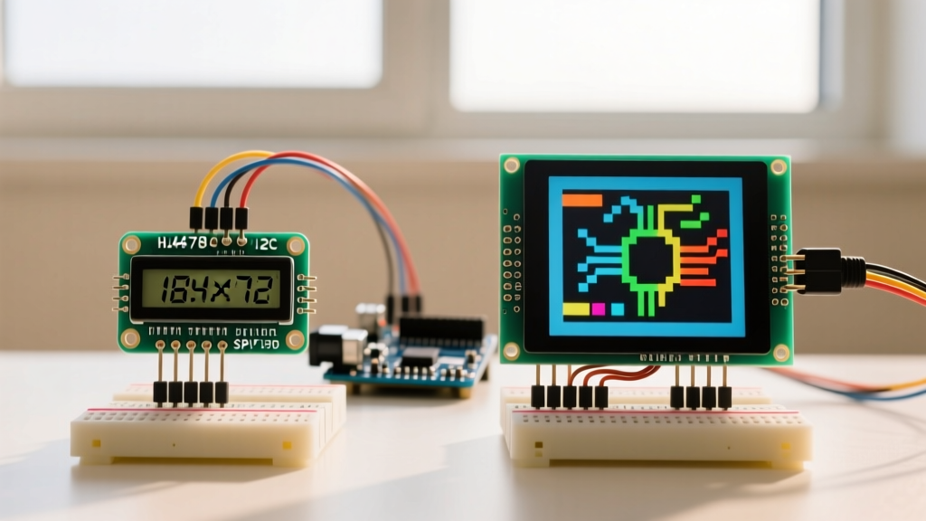
When makers and engineers search for an lcd panel arduino solution, they are typically met with two vastly different generations of display technology. On one side sits the venerable HD44780 character LCD, a staple of DIY electronics since the early 2000s. On the other side is the ILI9341 TFT LCD, a high-resolution, full-color graphic display that bridges the gap between basic microcontrollers and modern smartphones.
Choosing between a character display and a Thin-Film Transistor (TFT) panel is not merely a matter of aesthetics; it fundamentally dictates your microcontroller's memory architecture, wiring complexity, and logic-level requirements. As of 2026, while ESP32 and Raspberry Pi Pico boards have largely democratized high-speed SPI displays, the classic 5V Arduino Uno (ATmega328P) remains heavily used. This guide provides a rigorous, component-level comparison to help you select the exact LCD panel for your next peripheral integration.
Quick Decision Matrix
- Choose HD44780 (I2C): For simple telemetry, text-based menus, low-SRAM environments (ATmega328P), and rapid prototyping where color is irrelevant.
- Choose ILI9341 (SPI TFT): For GUI dashboards, real-time graphing, image rendering, and projects utilizing 3.3V MCUs with higher clock speeds (ESP32, Teensy 4.1).
Contender 1: HD44780 16x2 Character LCD (I2C Backpack)
The standard 16x2 character LCD relies on the Hitachi HD44780 controller. While original parallel versions required 6 GPIO pins, modern implementations almost universally use a PCF8574 I2C expander backpack, reducing the interface to just two data lines (SDA/SCL) plus power.
Technical Specifications & 2026 Market Reality
- Controller: HD44780 (Display) + PCF8574 or PCF8574A (I2C Expander)
- Resolution: 16 columns x 2 rows (Text only, 5x8 pixel character grid)
- Logic Level: 5V native (Perfect for Arduino Uno/Mega)
- Interface: I2C (Up to 100kHz standard mode)
- Average Pricing (2026): $4.50 – $6.50 USD for assembled units with backpacks.
Edge Cases & Failure Modes
The most common failure mode when integrating an I2C LCD panel with an Arduino is the "black boxes on the first row" issue. This is rarely a defective screen; it is almost always a contrast voltage mismatch or an I2C address conflict. The PCF8574 backpack features a 10kΩ trimpot that must be adjusted to set the V0 (contrast) pin voltage. Furthermore, I2C addresses vary by manufacturer: boards with the PCF8574 chip default to 0x27, while those with the PCF8574A chip default to 0x3F. Always run an I2C scanner sketch before hardcoding addresses in your LiquidCrystal library initialization.
Contender 2: ILI9341 2.8" TFT LCD (SPI Interface)
The ILI9341 is a highly integrated System-on-Chip (SoC) display driver designed for amorphous TFT LCD panels. It supports 240x320 pixel resolution with 16-bit color depth (65,536 colors), making it the gold standard for advanced Arduino GUI projects.
Technical Specifications & 2026 Market Reality
- Controller: ILI9341 (Integrated Gate/Source Driver & GRAM)
- Resolution: 240 x 320 pixels
- Logic Level: 3.3V strict (Requires level shifting for 5V Arduinos)
- Interface: 4-Wire SPI (MOSI, MISO, SCK, CS) + DC and RST pins
- Average Pricing (2026): $12.00 – $18.00 USD (Resistive touch versions sit at the higher end).
The 5V vs 3.3V Logic Level Trap
This is where most beginners destroy their TFT panels. The Arduino Uno operates at 5V logic. The ILI9341 SPI pins are strictly 3.3V tolerant. While some breakout boards include an onboard 3.3V LDO to power the LED backlight and internal logic, the SPI data lines (MOSI, SCK, CS, DC) connect directly to the controller's CMOS inputs. Feeding 5V into these pins will cause gate oxide degradation, eventually resulting in a permanently white or corrupted screen.
Expert Tip: Never use a simple resistor voltage divider for high-speed SPI lines; the parasitic capacitance will distort the square wave, causing data corruption at clock speeds above 4MHz. Instead, use a dedicated logic level translator IC like the TI CD4050B hex buffer or a BSS138 bidirectional MOSFET module.
Head-to-Head Comparison Matrix
| Feature | HD44780 16x2 (I2C) | ILI9341 2.8" TFT (SPI) |
|---|---|---|
| Display Type | Alphanumeric Character | Full-Color Graphic (RGB) |
| Memory Footprint | ~80 bytes (DDRAM) | 153.6 KB (Internal GRAM) |
| MCU SRAM Required | Negligible (< 50 bytes) | High (Requires streaming or buffering) |
| Refresh Rate | Slow (Flicker on full redraw) | Up to 60Hz (via DMA on ESP32) |
| Wiring Complexity | Low (4 wires) | High (6-8 wires + level shifting) |
Software Overhead: SRAM and the Framebuffer Problem
Understanding how an lcd panel arduino setup handles memory is critical for firmware stability. The ATmega328P (Arduino Uno) possesses a mere 2KB of SRAM. A single 240x320 frame in 16-bit color requires 153,600 bytes (150KB). You cannot store a full framebuffer in the Uno's memory.
Direct Streaming vs. DMA Buffering
When using the Adafruit GFX library on an 8-bit AVR Arduino, the library streams pixel data directly over the SPI bus in real-time. While this bypasses the SRAM limitation, it blocks the CPU during screen redraws, making real-time sensor polling difficult. Conversely, if you upgrade to an ESP32-S3, you can utilize Direct Memory Access (DMA) and external PSRAM, allowing the MCU to offload an entire 150KB framebuffer to the ILI9341 in the background while the main core continues processing sensor interrupts.
Troubleshooting Common TFT Failure Modes
If you opt for the ILI9341 TFT panel, be prepared to troubleshoot these specific hardware edge cases:
- The "White Screen of Death": This indicates the backlight is receiving power, but the SPI initialization sequence failed. Check your
DC(Data/Command) pin wiring. If the DC pin is floating or incorrectly mapped, the display interprets initialization commands as pixel data. - SPI Clock Speed Degradation: If you are using standard 10cm Dupont jumper wires, parasitic capacitance will cause data corruption at the default 24MHz or 40MHz SPI clock speeds. In your initialization code, manually drop the SPI divider. For an Arduino Uno, use
SPI.setClockDivider(SPI_CLOCK_DIV4);to force a stable 4MHz clock. - Backlight Dimming/Thermal Throttling: The LED backlight on 2.8" panels draws roughly 120mA at 3.3V. Do not attempt to power the
LEDpin directly from the Arduino's 3.3V voltage regulator, as it will overheat and trigger thermal shutdown. Drive the backlight pin using a logic-level N-channel MOSFET (like the IRLB8721) connected to the 5V rail.
Final Verdict: Which Setup Wins?
There is no universal "best" lcd panel arduino configuration; there is only the right tool for the specific system constraints.
If your project is an environmental monitor logging data to an SD card, or a simple PID temperature controller, the HD44780 I2C is unmatched. It requires virtually no CPU overhead, operates natively at 5V, and costs less than a cup of coffee.
However, if you are building a smart home thermostat, an oscilloscope, or a motor-control dashboard requiring color-coded alerts and touch input, the ILI9341 TFT is mandatory. Just ensure you pair it with a 3.3V microcontroller like the ESP32 or Arduino Nano 33 IoT to bypass logic-level translation headaches and unlock hardware SPI DMA streaming.