
Introduction to Pulse Width Modulation (PWM)
Microcontrollers are inherently digital devices; they understand only two states: HIGH (typically 5V or 3.3V) and LOW (0V). However, many real-world peripherals, such as LED lighting arrays and DC motors, require analog-like control to vary brightness or speed. This is where Pulse Width Modulation (PWM) becomes essential. By rapidly toggling a digital pin on and off at a specific frequency and varying the ratio of the 'on' time to the 'off' time (the duty cycle), we can simulate an analog voltage.
The Core Concept: Imagine flipping a light switch on and off 500 times a second. If you leave it on for half the time and off for half the time, the human eye perceives the light as being at 50% brightness. This is a 50% duty cycle.
In this comprehensive Arduino PWM example guide, we will move beyond basic theory. We will explore how to implement PWM on modern 2026 development boards like the Arduino Uno R4 Minima and the Nano ESP32, wire a fading LED circuit, and interface a high-current DC motor using an H-bridge driver.
Hardware Requirements and 2026 Board Pricing
While the classic ATmega328P-based Uno R3 is still found in many classrooms, the industry standard for new designs has shifted toward 32-bit architectures. Below is the recommended hardware list for this tutorial, reflecting current market pricing.
| Component | Model / Specification | Estimated Cost (USD) | Role in Circuit |
|---|---|---|---|
| Microcontroller | Arduino Uno R4 Minima (Renesas RA4M1) | $27.50 | Main PWM signal generator |
| Alternative MCU | Arduino Nano ESP32 (ESP32-S3) | $21.00 | High-resolution PWM alternative |
| Motor Driver | L298N Dual H-Bridge Module | $4.50 | Current amplification for DC motor |
| Actuator | 12V 775 DC Spindle Motor | $12.00 | Target peripheral for speed control |
| Passive Components | 220Ω Resistor, 5mm Red LED | $0.10 | Visual PWM indicator |
Understanding the analogWrite() Function
The primary mechanism for generating PWM signals in the Arduino ecosystem is the analogWrite(pin, value) function. According to the official Arduino language reference, this function writes an analog value (PWM wave) to a pin. However, its behavior varies significantly depending on the underlying silicon.
Resolution Differences: 8-bit vs. 12-bit
On legacy 8-bit boards (Uno R3, Nano), the value parameter ranges from 0 to 255. A value of 0 represents a 0% duty cycle (0V average), and 255 represents a 100% duty cycle (5V average). However, modern 32-bit boards like the Uno R4 Minima and Nano ESP32 natively support higher resolution PWM. By default, the Arduino core maps analogWrite() to 8-bit for backward compatibility, but you can unlock 12-bit resolution (0 to 4095) using analogWriteResolution(12) in your setup block. This provides 16 times finer control over motor acceleration curves and LED dimming profiles.
PWM Pin Mapping and Timer Frequencies
Not all digital pins support hardware PWM. You must look for the tilde (~) symbol on the board silkscreen, though newer boards like the Uno R4 Minima support PWM on almost all digital pins via flexible timer routing.
| Board Model | Default PWM Resolution | Default Frequency | Primary PWM Pins |
|---|---|---|---|
| Uno R3 (ATmega328P) | 8-bit (0-255) | 490 Hz (980 Hz on pins 5, 6) | 3, 5, 6, 9, 10, 11 |
| Uno R4 Minima (RA4M1) | 8-bit (0-255) | 490 Hz | Pins 0-13 (Highly flexible) |
| Nano ESP32 (ESP32-S3) | 8-bit (0-255) | 5000 Hz | All digital pins via LEDC peripheral |
Arduino PWM Example 1: Fading an LED
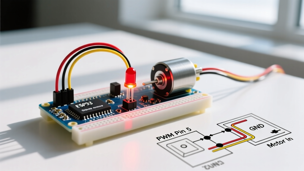
Let us start with a foundational circuit. We will smoothly fade a 5mm LED using a triangular wave pattern.
Wiring the LED Circuit
- Connect the anode (long leg) of the 5mm LED to a 220Ω current-limiting resistor.
- Connect the other end of the resistor to Pin 9 on your Arduino.
- Connect the cathode (short leg, flat edge) of the LED directly to the GND pin.
Engineering Note: Why 220Ω? Assuming a 5V logic HIGH and a typical red LED forward voltage (Vf) of 2.0V, the voltage drop across the resistor is 3.0V. Using Ohm's Law (R = V/I), targeting a safe 15mA current yields R = 3.0 / 0.015 = 200Ω. A standard 220Ω resistor is the closest E12 series value and ensures the pin does not exceed its 20mA continuous current rating.
The Fading Code
const int ledPin = 9;
int brightness = 0;
int fadeAmount = 5;

void setup() {
  pinMode(ledPin, OUTPUT);
}

void loop() {
  analogWrite(ledPin, brightness);
  brightness = brightness + fadeAmount;

  if (brightness <= 0 || brightness >= 255) {
    fadeAmount = -fadeAmount;
  }
  delay(30);
}
This code increments the duty cycle by 5 units every 30 milliseconds, creating a smooth 'breathing' effect. For more advanced lighting projects, consider exploring the SparkFun PWM tutorial which covers gamma correction for human eye perception.
Arduino PWM Example 2: DC Motor Speed Control
Microcontroller pins can only source about 20mA to 45mA of current. A standard 12V 775 DC motor draws upwards of 1.5A under load. Connecting a motor directly to an Arduino pin will instantly destroy the microcontroller's voltage regulator and silicon die. We must use an intermediary power stage, such as the L298N Dual H-Bridge.
Wiring the L298N Motor Driver
- 12V Power Supply: Connect to the L298N 12V terminal and GND terminal.
- Common Ground: Run a jumper wire from the L298N GND to the Arduino GND. Failure to share a common ground is the #1 cause of erratic PWM behavior in beginner projects.
- Logic Control: Connect L298N ENA (Enable A) to Arduino Pin 9 (PWM pin).
- Direction Control: Connect IN1 to Arduino Pin 8, and IN2 to Arduino GND (for unidirectional control).
- Motor Terminals: Connect the 775 Motor wires to OUT1 and OUT2.
Motor Control Code
const int enaPin = 9;
const int in1Pin = 8;

void setup() {
  pinMode(enaPin, OUTPUT);
  pinMode(in1Pin, OUTPUT);
  digitalWrite(in1Pin, HIGH); // Set direction forward
}

void loop() {
  // Ramp up motor speed
  for (int speed = 0; speed <= 255; speed += 5) {
    analogWrite(enaPin, speed);
    delay(100);
  }
  // Hold at max speed for 2 seconds
  delay(2000);

  // Ramp down
  for (int speed = 255; speed >= 0; speed -= 5) {
    analogWrite(enaPin, speed);
    delay(100);
  }
  delay(2000);
}
Troubleshooting Motor Whine: The Frequency Problem
When you run the above code on a classic Uno R3, you will likely hear a high-pitched, annoying whining noise from the motor. This acoustic noise occurs because the default PWM frequency on Pin 9 is roughly 490 Hz, which falls squarely in the range of human hearing. The motor's stator laminations physically vibrate at this frequency.
The Expert Fix: You can manipulate the hardware timers directly to push the PWM frequency into the ultrasonic range (above 20 kHz). On the ATmega328P, Pin 9 is controlled by Timer 1. By altering the prescaler bits in the TCCR1B register inside your setup() function, you can change the frequency to 31,250 Hz, rendering the motor completely silent:
void setup() {
  // Set Timer 1 prescaler to 1 (31.25 kHz PWM on pins 9 & 10)
  TCCR1B = TCCR1B & B11111000 | B00000001;
  pinMode(enaPin, OUTPUT);
  pinMode(in1Pin, OUTPUT);
}
Warning: Modifying Timer 1 will break the millis() and delay() functions if they rely on that specific timer, though on the ATmega328P, millis() uses Timer 0. Always consult the Arduino PWM Foundations guide before altering timer registers.
Common Failure Modes and Edge Cases
When integrating PWM peripherals, engineers frequently encounter the following edge cases:
- Using Non-PWM Pins: Calling
analogWrite()on a standard digital pin (like Pin 12 on an Uno R3) will not output a PWM wave. Instead, it will output a solid HIGH if the value is > 127, or LOW if <= 127. - Motor Stalling at Low Duty Cycles: DC motors require a minimum threshold of current to overcome static friction and cogging torque. A PWM value of 10 (out of 255) might provide enough average voltage to energize the coils, but not enough torque to spin the shaft, resulting in overheating. Always map your software inputs to start at the motor's actual 'stall threshold' (usually around 15-20% duty cycle).
- Flyback Voltage Spikes: When PWM switches off, the inductive load of a DC motor generates a reverse voltage spike. While the L298N has built-in flyback diodes, cheap clone modules often use under-specced diodes that fail over time. For industrial 2026 applications, consider upgrading to a MOSFET-based driver like the BTS7960 (43A capacity, ~$14.00) which handles inductive kickback far more gracefully.
Summary
Mastering the analogWrite() function is a rite of passage for embedded systems developers. Whether you are dimming a simple indicator LED or profiling the acceleration curve of a 12V spindle motor via an H-bridge, understanding the underlying timer resolution, frequency limitations, and hardware current limits separates fragile prototypes from robust, production-ready electronics.