
Understanding the KY-026 Flame Sensor Module
When building environmental monitoring or safety projects, integrating a flame detector sensor Arduino setup is a classic and highly educational milestone. The most ubiquitous module on the market is the KY-026 (and its sibling, the KY-029). Priced typically between $1.50 and $3.00, this module offers both digital and analog outputs, making it an incredibly versatile peripheral for beginners and advanced makers alike.
The Physics of IR Detection
At the heart of the KY-026 is a 5mm infrared (IR) photodiode. Unlike standard LEDs that emit light, this photodiode is designed to absorb it. It is highly sensitive to light wavelengths ranging from 760 nm to 1100 nm. Because open flames (from matches, lighters, or wood fires) emit heavily in the near-infrared spectrum, the photodiode's internal resistance drops proportionally to the intensity of the IR radiation it receives.
The LM393 Comparator Circuit
The raw signal from a photodiode is analog and continuous. To make it useful for digital microcontrollers, the KY-026 module routes the photodiode's voltage divider signal into an LM393 Dual Differential Comparator. The LM393 compares the sensor's voltage against a reference voltage set by an onboard 10K ohm trimpot (potentiometer). If the IR intensity crosses the threshold, the comparator's open-collector output pulls the Digital Out (DO) pin LOW.
2026 Component Checklist & Pricing
To build a reliable fire-detection prototype, you will need the following components. Pricing reflects standard hobbyist market rates for 2026.
| Component | Model / Specification | Estimated Price (USD) |
|---|---|---|
| Flame Sensor Module | KY-026 (4-pin version with LM393) | $1.50 - $2.50 |
| Microcontroller | Arduino Uno R4 Minima (or standard Rev3) | $20.00 - $29.00 |
| Active Buzzer | 5V Piezo Active Buzzer (KY-012) | $1.00 |
| Jumper Wires | M-to-F and M-to-M Dupont wires | $3.00 |
Pinout and Wiring Matrix
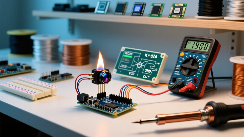
The KY-026 typically features a 4-pin header. Proper voltage matching is critical; while the LM393 can operate from 3.3V to 5V, matching your microcontroller's logic level ensures clean digital transitions.
| KY-026 Pin | Function | Arduino Uno R4 / Rev3 Pin |
|---|---|---|
| VCC | Power Supply (3.3V - 5V) | 5V (or 3.3V depending on board logic) |
| GND | Ground Reference | GND |
| DO | Digital Output (Active LOW) | Digital Pin 2 |
| AO | Analog Output (0V to VCC) | Analog Pin A0 |
Step-by-Step Wiring Guide
- Power the Module: Connect the VCC pin on the KY-026 to the 5V pin on the Arduino. Connect the GND pin to any Arduino GND pin.
- Connect Digital Out: Run a jumper wire from the DO pin on the sensor to Digital Pin 2 on the Arduino. This pin will trigger when a flame crosses the calibrated threshold.
- Connect Analog Out: Run a jumper wire from the AO pin to Analog Pin A0. This provides a continuous reading of IR intensity, useful for estimating flame proximity.
- Attach the Buzzer (Optional): Connect the positive (long) leg of the active buzzer to Digital Pin 8, and the negative leg to GND.
Arduino Code: Digital and Analog Reading
The following C++ sketch reads both the digital threshold trigger and the raw analog proximity data. Note: If you are using the newer Arduino Uno R4 Minima, its ADC is 14-bit by default (0-16383), whereas older Rev3 boards use a 10-bit ADC (0-1023). The code below uses analogReadResolution(10) to ensure backward compatibility and consistent mapping across both generations.
// Flame Detector Sensor Arduino Interfacing Code
const int DO_PIN = 2;    // Digital Out connected to Pin 2
const int AO_PIN = A0;   // Analog Out connected to A0
const int BUZZER_PIN = 8; // Buzzer connected to Pin 8

void setup() {
  Serial.begin(9600);

  // Set ADC to 10-bit resolution for consistency across Uno R3 and R4
  analogReadResolution(10);

  pinMode(DO_PIN, INPUT);
  pinMode(BUZZER_PIN, OUTPUT);

  digitalWrite(BUZZER_PIN, LOW); // Ensure buzzer is off initially
  Serial.println("KY-026 Flame Sensor Initialized...");
}

void loop() {
  int digitalVal = digitalRead(DO_PIN);
  int analogVal = analogRead(AO_PIN);

  // The DO pin is Active LOW (LOW means flame detected)
  if (digitalVal == LOW) {
    Serial.println("[ALARM] Flame Detected! (Digital Threshold Crossed)");
    digitalWrite(BUZZER_PIN, HIGH);
  } else {
    digitalWrite(BUZZER_PIN, LOW);
  }

  // Print Analog IR Intensity (Lower value = Higher IR intensity / Closer flame)
  Serial.print("IR Intensity Raw: ");
  Serial.print(analogVal);

  if (analogVal < 300) {
    Serial.println(" | Status: Proximity High (Close Flame)");
  } else if (analogVal < 700) {
    Serial.println(" | Status: Proximity Medium");
  } else {
    Serial.println(" | Status: No significant IR source");
  }

  delay(500); // Poll twice per second
}
Calibration: Tuning the LM393 Potentiometer
Beginners often plug in the KY-026 and immediately experience false triggers or total unresponsiveness. This is almost always a calibration issue. The blue trimpot on the module adjusts the reference voltage fed into the LM393's inverting input.
- To increase sensitivity (trigger on smaller/distant flames): Turn the potentiometer screw counter-clockwise until the onboard status LED turns OFF, then nudge it slightly back.
- To decrease sensitivity (prevent false alarms): Turn the screw clockwise. This raises the threshold, requiring a larger, hotter, or closer flame to pull the DO pin LOW.
Pro-Tip: Use a ceramic or plastic adjustment tool rather than a metal screwdriver. Metal tools can introduce parasitic capacitance and slightly alter the voltage divider network while you are tuning it.
Troubleshooting & Environmental Edge Cases
Real-world deployment of IR flame sensors introduces several environmental variables that lab testing often misses. Understanding these edge cases is what separates a novice from an embedded systems engineer.
1. Sunlight and Incandescent Interference
The sun is a massive emitter of broadband radiation, including the 760-1100nm IR spectrum. If your sensor is placed near a south-facing window, direct sunlight will saturate the photodiode, pulling the analog value to near-zero and permanently triggering the digital alarm. Similarly, traditional incandescent and halogen bulbs emit heavy IR. Solution: Use physical shielding (a small 3D-printed hood) to restrict the sensor's field of view, or swap to UV-based flame sensors (like the GUVA-S12SD) for outdoor applications.
2. The Inverse Square Law Limitation
IR radiation intensity obeys the inverse square law. A standard lighter flame will easily trigger the KY-026 at 15 cm. However, at 60 cm, the IR intensity drops to roughly 6% of its original strength, falling below the noise floor of the cheap photodiode. Do not expect this $2 sensor to detect a fire across a large warehouse; it is strictly a proximity flame detector.
3. LED Flashlights Do Not Trigger It
Many beginners test their wiring by shining a bright white LED flashlight into the sensor and wonder why it fails. Modern white LEDs use a blue die with a yellow phosphor coating; they emit almost zero near-infrared radiation. Always test with an actual butane lighter or a wooden match.
Safety Warning: Hobby vs. Life-Safety Systems
CRITICAL NOTICE: The KY-026 and similar hobbyist modules are designed for educational and prototype use only. They lack the redundancy, self-testing circuitry, and UL/FM certifications required for life-safety fire alarms. Never rely on an Arduino-based IR sensor as your primary home fire detection system. Always adhere to local building codes and install certified commercial smoke and heat detectors compliant with NFPA 72 standards for actual residential or commercial protection.
Next Steps: Expanding Your Peripheral Network
Once you have mastered the flame detector sensor Arduino interface, consider combining it with an MQ-2 combustible gas sensor. While the KY-026 detects the physical flames, the MQ-2 detects the unburnt propane or natural gas before ignition, allowing you to build a comprehensive, multi-layered environmental safety node for your smart home IoT network.