
Why Datasheets Dictate Your Stepper Motor Code in Arduino
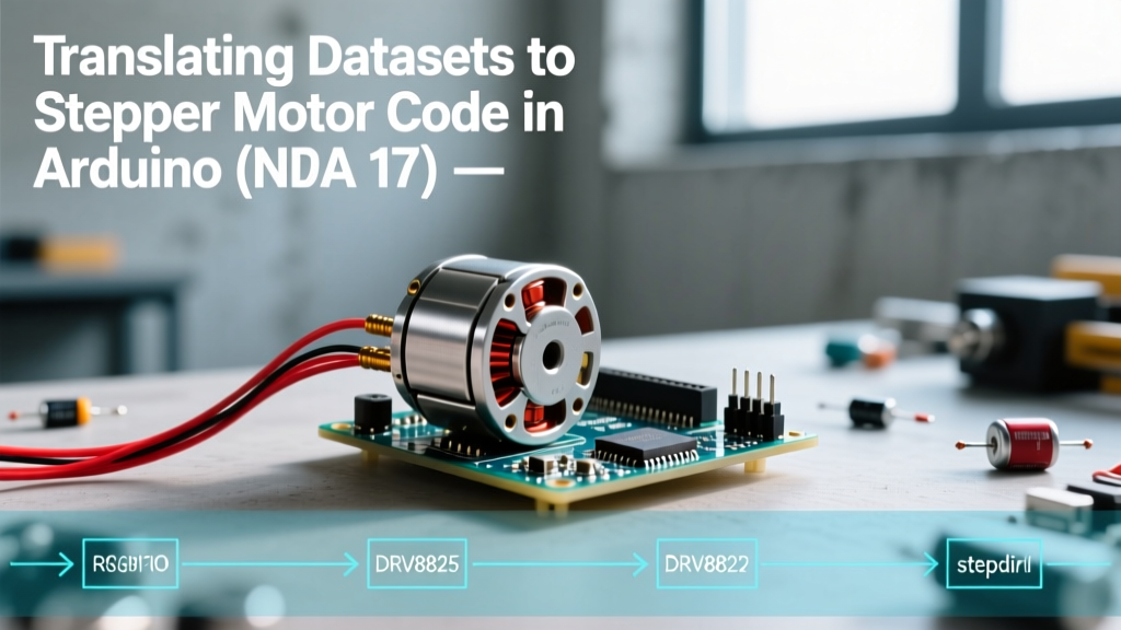
Most online tutorials provide copy-paste snippets for controlling stepper motors, but they rarely explain the physics and electrical constraints hiding in the component datasheets. When your NEMA 17 motor stalls, overheats, or loses position in a CNC or 3D printing application, the culprit is usually a disconnect between the hardware specifications and the software logic. As of 2026, the 17HS4401 NEMA 17 stepper motor (retailing around $12 to $15) paired with a DRV8825 driver (about $3.50) remains the industry standard for DIY precision motion. In this guide, we will dissect the datasheets for both components and translate their hard limits into robust, production-ready stepper motor code in Arduino.
Decoding the NEMA 17 (17HS4401) Motor Datasheet
Before writing a single line of code, we must extract three critical parameters from the 17HS4401 datasheet: step angle, rated current, and rotor inertia.
- Step Angle: The datasheet specifies a 1.8° step angle. This means one full revolution requires exactly 200 full steps (360 / 1.8 = 200). This value forms the base multiplier for all your speed and distance calculations.
- Rated Current: The 17HS4401 is rated at 1.5A per phase. Pushing more current than this will not yield proportional torque gains; it will simply saturate the magnetic core and overheat the windings.
- Rotor Inertia: Listed at 54 g·cm². This is the most ignored spec in Arduino projects. Inertia dictates how fast the motor can accelerate before the rotor physically lags behind the stator's magnetic field, resulting in skipped steps.
Hardware-Software Bridge: The datasheet's 1.5A current rating requires you to physically tune the current limit potentiometer on your driver board before uploading your code. For the DRV8825, the formula is Vref = Imax / 2. Therefore, you must use a multimeter to set the Vref test point to exactly 0.75V. No amount of software tweaking can fix a misconfigured hardware current limit.
The DRV8825 Driver: Timing and Microstepping Constraints
The Texas Instruments DRV8825 datasheet reveals the electrical timing constraints that your Arduino must respect. Unlike the older A4988, the DRV8825 supports up to 1/32 microstepping, allowing for smoother motion and reduced acoustic noise. However, microstepping fundamentally changes the step resolution your code must target.
If you configure the DRV8825 for 1/16 microstepping, your code must output 3,200 pulses per revolution (200 full steps × 16). Furthermore, the datasheet specifies a minimum STEP pulse width of 1.9 µs. If you use raw digitalWrite() commands without microsecond delays, modern 32-bit microcontrollers might pulse too fast for the driver's logic gates to register, causing missed steps.
Microstepping Truth Table & Arduino Pin Mapping
To set the microstepping resolution, you must wire the MS1, MS2, and MS3 pins on the DRV8825 to Arduino digital pins (or hardwire them to VCC/GND). Below is the mapping table derived directly from the Pololu DRV8825 carrier board documentation.
| MS1 | MS2 | MS3 | Resolution | Steps per Revolution | Code Multiplier |
|---|---|---|---|---|---|
| LOW | LOW | LOW | Full Step | 200 | x1 |
| HIGH | LOW | LOW | 1/2 Step | 400 | x2 |
| LOW | HIGH | LOW | 1/4 Step | 800 | x4 |
| HIGH | HIGH | LOW | 1/8 Step | 1600 | x8 |
| HIGH | HIGH | HIGH | 1/16 Step | 3200 | x16 |
Writing Production-Ready Stepper Motor Code in Arduino
For real-world applications, the built-in Arduino Stepper.h library is inadequate because it blocks the main loop and lacks acceleration profiling. Instead, we use the AccelStepper library, which handles non-blocking pulse generation and respects the physical inertia limits defined in the motor datasheet.
Below is the optimized code for a 17HS4401 motor driven by a DRV8825 set to 1/16 microstepping. Notice how the datasheet specs directly inform the setMaxSpeed() and setAcceleration() parameters.
#include <AccelStepper.h>

// Pin Definitions
#define STEP_PIN 3
#define DIR_PIN 4
#define MS1_PIN 5
#define MS2_PIN 6
#define MS3_PIN 7

// Initialize AccelStepper with the DRIVER interface
AccelStepper stepper(AccelStepper::DRIVER, STEP_PIN, DIR_PIN);

void setup() {
  // Configure Microstepping Pins for 1/16 Step (HIGH, HIGH, HIGH)
  pinMode(MS1_PIN, OUTPUT);
  pinMode(MS2_PIN, OUTPUT);
  pinMode(MS3_PIN, OUTPUT);
  digitalWrite(MS1_PIN, HIGH);
  digitalWrite(MS2_PIN, HIGH);
  digitalWrite(MS3_PIN, HIGH);

  // Datasheet Translation:
  // Max Speed: 3200 steps/sec = 1 rev/sec (safe continuous speed for 17HS4401)
  stepper.setMaxSpeed(3200);

  // Acceleration: Based on 54 g·cm² rotor inertia.
  // 1600 steps/sec^2 prevents the rotor from stalling during startup.
  stepper.setAcceleration(1600);

  // Set minimum pulse width to satisfy DRV8825 1.9µs datasheet requirement
  stepper.setMinPulseWidth(5); // 5 microseconds for safety margin
}

void loop() {
  // Move exactly 2 full revolutions (6400 microsteps)
  if (stepper.distanceToGo() == 0) {
    stepper.moveTo(6400);
  }

  // Non-blocking step execution
  stepper.run();
}
Edge Cases: When Code Ignores the Datasheet
Writing stepper motor code in Arduino without respecting the hardware datasheet leads to specific, predictable failure modes. Understanding these will save you hours of debugging.
1. Mid-Band Resonance Stalls
Stepper motors suffer from a phenomenon called mid-band resonance, typically occurring between 500 and 1,000 full steps per second. At these frequencies, the rotor's natural oscillation aligns with the step frequency, causing a catastrophic drop in torque and resulting in a complete stall. The Fix: Use the DRV8825's microstepping capabilities to push the pulse frequency above the resonance band, or program your Arduino acceleration curve to ramp through this speed zone as rapidly as possible.
2. Thermal Shutdown Looping
The DRV8825 datasheet notes an internal thermal shutdown threshold of roughly 150°C. If your code commands high holding torque (keeping the coils energized while stationary) and your Vref is set too high, the driver will overheat, shut down, cool off, and restart in a continuous loop. The Fix: Implement an enablePin in your code to cut power to the driver's ENABLE pin when the motor is idle for more than 5 seconds, or reduce the Vref to 60% of the motor's rated current for holding phases.
3. Direction Setup Time Violations
The DRV8825 requires a 650 ns setup time between changing the DIR pin and issuing the first STEP pulse. If your Arduino code changes direction and immediately fires a step pulse in the next clock cycle, the driver may misinterpret the direction, causing your mechanism to crash into its limit switch. The AccelStepper library handles this timing automatically, which is why it is heavily preferred over raw GPIO toggling for precision peripherals.
Summary
Mastering stepper motor code in Arduino is less about memorizing syntax and more about translating physical datasheet constraints into software limits. By matching the 17HS4401's inertia profile to your acceleration variables, respecting the DRV8825's microsecond timing requirements, and utilizing non-blocking libraries, you transform a jittery DIY prototype into a reliable, industrial-grade motion system.