
The Problem with Open-Loop Steppers in Precision Applications
Integrating a stepper motor driver with Arduino is a foundational skill in DIY CNC, 3D printing, and automated camera sliders. However, standard open-loop stepper systems suffer from a critical flaw: they assume the motor has successfully completed every commanded step. If mechanical resistance exceeds the motor's holding torque, the system experiences 'lost steps,' resulting in cumulative positional drift. In 2026, relying purely on open-loop counting for precision automation is considered an outdated practice for high-reliability projects.
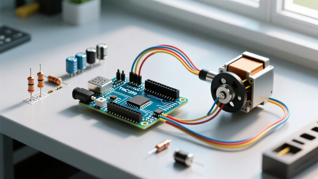
To achieve true positional accuracy, we must close the loop using physical sensors. This tutorial details how to pair the ultra-silent Trinamic TMC2209 stepper driver with an Arduino Uno and an A3144 Hall effect sensor to create a robust, auto-homing linear actuator. We will cover exact wiring schematics, VREF calibration, electromagnetic interference (EMI) mitigation, and the C++ code required for sensor-triggered homing.
Component Breakdown: TMC2209 vs. Legacy Drivers
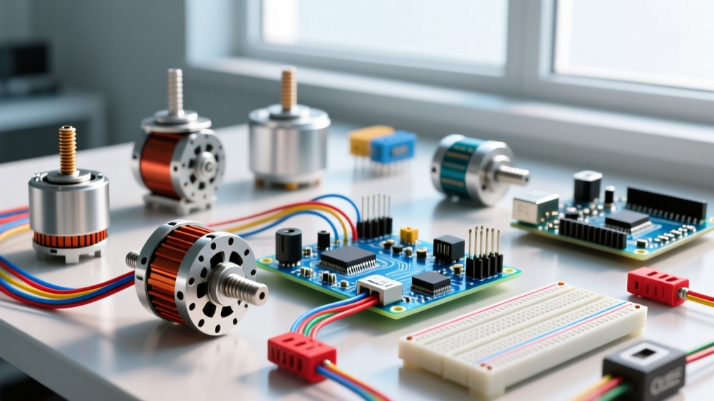
While the A4988 and DRV8825 dominated the maker space a decade ago, modern projects demand quieter operation and better thermal management. The TMC2209 utilizes StealthChop2 technology for inaudible operation and supports StallGuard4 for sensorless homing, though physical Hall sensors remain superior for high-load, low-speed homing accuracy.
| Driver Model | Max Continuous Current | Microstepping | 2026 Avg. Module Price | Acoustic Noise |
|---|---|---|---|---|
| A4988 (Legacy) | 1.0A (with cooling) | 1/16 | $2.50 - $4.00 | High (Whine) |
| DRV8825 | 1.5A (with cooling) | 1/32 | $3.50 - $5.50 | Moderate |
| TMC2209 (BTT V1.2) | 2.0A (passive cooling) | 1/256 | $8.00 - $14.00 | Silent (StealthChop) |
Note: For this tutorial, we use the BigTreeTech (BTT) TMC2209 V1.2 module, which features 0.11Ω sense resistors and an integrated 5V logic regulator, making it directly compatible with 5V Arduino microcontrollers.
Precision Wiring: Power, Logic, and Sensor Integration
Wiring a TMC2209 requires careful separation of high-current motor phases and low-voltage logic signals. The A3144 Hall effect sensor acts as a unipolar magnetic switch, outputting a LOW signal when a south-pole magnet is nearby.
TMC2209 to Arduino Pinout
- VDD (Logic): Connect to Arduino 5V
- GND: Connect to Arduino GND and Power Supply GND (Star grounding is mandatory)
- VM (Motor Power): Connect to 12V or 24V DC PSU positive terminal
- STEP: Connect to Arduino Pin 3
- DIR: Connect to Arduino Pin 4
- EN: Connect to Arduino Pin 8 (Active LOW)
A3144 Hall Effect Sensor Wiring
The A3144 features an open-collector NPN output. This means it can pull the signal line to ground, but it cannot drive it HIGH. You must use a pull-up resistor.
- VCC: Arduino 5V
- GND: Arduino GND
- OUT: Arduino Pin 2 (Interrupt capable). Connect a 10kΩ resistor between OUT and 5V.
Expert Callout: Sensor Pull-Up and EMI Mitigation
Stepper motor PWM switching generates severe Electromagnetic Interference (EMI). If your Hall sensor signal wire runs parallel to the stepper motor coils, the induced noise will cause false triggers, making the Arduino think the limit switch has been hit. Always use a 100nF ceramic decoupling capacitor directly across the sensor's VCC and GND pins, and route the sensor cable as a twisted pair to reject common-mode noise.
VREF Calibration for NEMA 17 Motors
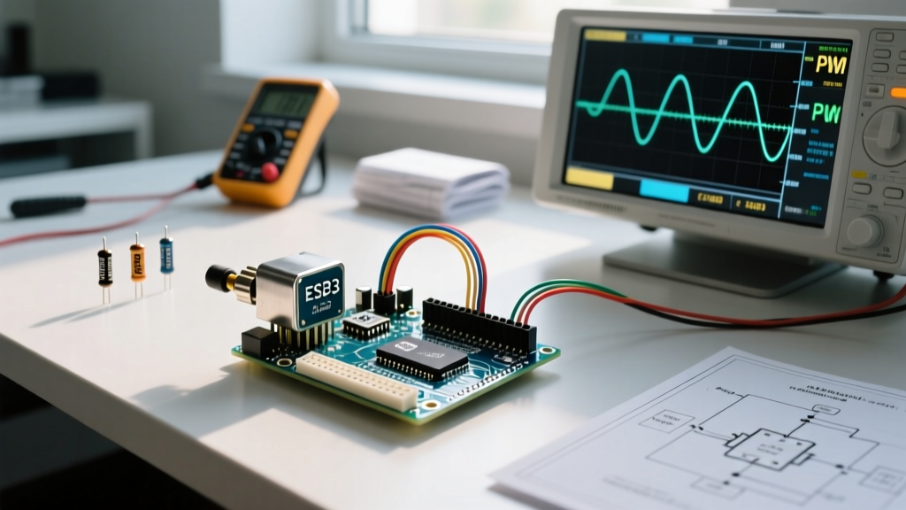
Before uploading any code, you must calibrate the driver's current limit using the VREF potentiometer. Supplying too much current will overheat your NEMA 17 motor (potentially demagnetizing the rotor if it exceeds 80°C), while too little current will cause skipped steps during the homing routine.
For the BTT TMC2209 V1.2 with 0.11Ω sense resistors, the formula is:
VREF = RMS_Current × 0.71
If your NEMA 17 is rated for 1.5A RMS, your target VREF is 1.06V. Power the driver's logic (VDD) but leave the motor power (VM) disconnected for safety. Use a digital multimeter to measure the voltage between the VREF test pad and ground, adjusting the ceramic potentiometer with a non-magnetic screwdriver until you hit the target voltage.
Arduino Code: Sensor-Triggered Homing Routine
To manage the acceleration curves and step timing, we utilize the AccelStepper library, the industry standard for non-blocking stepper control. We will use an external interrupt to catch the Hall sensor trigger instantly, ensuring the motor stops within microseconds of hitting the magnetic limit.
#include <AccelStepper.h>

// Pin Definitions
#define STEP_PIN 3
#define DIR_PIN 4
#define EN_PIN 8
#define HALL_SENSOR_PIN 2

// Create AccelStepper object (1 = EasyDriver/StepStick driver interface)
AccelStepper stepper(1, STEP_PIN, DIR_PIN);

volatile bool homingComplete = false;
unsigned long lastDebounceTime = 0;
const long debounceDelay = 5; // 5ms software debounce

void setup() {
  Serial.begin(115200);

  pinMode(EN_PIN, OUTPUT);
  digitalWrite(EN_PIN, LOW); // Enable driver (Active LOW)

  pinMode(HALL_SENSOR_PIN, INPUT_PULLUP); // Internal pull-up as backup

  // Attach interrupt: Trigger on FALLING edge (when magnet pulls pin LOW)
  attachInterrupt(digitalPinToInterrupt(HALL_SENSOR_PIN), hallTriggered, FALLING);

  stepper.setMaxSpeed(2000);      // Steps per second
  stepper.setAcceleration(1000);  // Steps per second^2
  stepper.setCurrentPosition(0);
}

void loop() {
  if (!homingComplete) {
    runHomingSequence();
  } else {
    // Normal operation logic goes here
    stepper.moveTo(10000);
    stepper.run();
  }
}

void runHomingSequence() {
  // Move backwards (negative direction) slowly to find home
  stepper.setSpeed(-800);
  stepper.runSpeed();
}

// Interrupt Service Routine (ISR)
void hallTriggered() {
  unsigned long currentTime = millis();
  // Software debouncing inside ISR to prevent EMI bounce
  if ((currentTime - lastDebounceTime) > debounceDelay) {
    lastDebounceTime = currentTime;

    stepper.setCurrentPosition(0); // Reset coordinate system to 0
    stepper.stop();                // Immediate deceleration to 0
    homingComplete = true;
  }
}
Understanding the Homing Logic Flow
- Initialization: The driver is enabled, and the Arduino configures Pin 2 as an input with an internal pull-up resistor. The
attachInterrupt()function is bound to the FALLING edge. - Seeking: The
runHomingSequence()function commands the motor to move in the negative direction at a constant 800 steps/second. We avoid high speeds during homing to prevent mechanical overshoot. - Trigger & Debounce: When the neodymium magnet passes the A3144, the output transistor sinks current, pulling Pin 2 LOW. The ISR fires. A 5ms software debounce filter ignores any microsecond-level EMI spikes.
- Zeroing: The coordinate system is instantly reset to 0, and the
stop()command calculates a rapid deceleration curve to halt the motor safely without losing synchronicity.
Troubleshooting Edge Cases and Failure Modes
When integrating sensors with high-current inductive loads, theoretical wiring diagrams rarely survive first contact with a physical breadboard. Below are the most common failure modes encountered in 2026 DIY automation builds, along with their specific solutions.
- Motor Vibrates but Does Not Spin: This almost always indicates a wiring fault in the stepper coils. The TMC2209 requires the coils to be paired correctly (e.g., A1/A2 and B1/B2). Use a multimeter in continuity mode to identify the two coil pairs before connecting them to the 1A/1B and 2A/2B terminals.
- False Hall Sensor Triggers Mid-Travel: As mentioned, EMI from the stepper cables is inducing voltage in the sensor wire. Fix: Add a 100nF capacitor across the sensor power pins, use shielded cable for the sensor, and ensure your 12V/24V motor PSU ground is tied to the Arduino logic ground at exactly one point (star ground) to prevent ground loops.
- Motor Overheating During Hold: The TMC2209 holds full current when stationary by default. You can reduce the holding current via UART configuration, or simply toggle the
EN_PINto HIGH when the actuator reaches its target destination to cut power entirely and allow the motor to freewheel. - Positional Drift After Homing: If your system drifts after the homing routine is complete, your acceleration curve is too aggressive for the motor's torque curve. Lower the
setAcceleration()value in the AccelStepper configuration or increase the VREF slightly (by no more than 0.1V increments) to provide more low-speed torque.
For deeper insights into managing external hardware interrupts and timing constraints on AVR-based boards, consult the official Arduino Interrupt Documentation. Furthermore, reviewing the Analog Devices TMC2209 Datasheet will provide advanced UART configuration parameters if you decide to upgrade from hardware STEP/DIR control to fully programmable current scaling.
By combining the acoustic and thermal benefits of the TMC2209 with the hard positional certainty of a debounced Hall effect sensor, you elevate your Arduino project from a fragile prototype to a reliable, industrial-grade motion system.