
Beyond analogWrite: The Reality of Arduino PWM
When makers first search for an arduino pwm how to guide, they are almost universally directed to the analogWrite() function. While this native approach is perfect for fading a single LED or driving a basic DC motor, it quickly falls apart in complex projects. If you are building a 12-DOF hexapod, a high-resolution cinematic LED array, or a multi-zone automated greenhouse, the ATmega328P's native 6-channel, 8-bit hardware PWM becomes a severe bottleneck.
In 2026, the maker ecosystem offers robust external peripheral alternatives. This component comparison dives deep into native hardware timers versus dedicated external PWM integrated circuits (ICs) like the NXP PCA9685 and the Texas Instruments TLC5940, giving you the exact architectural data needed to choose the right peripheral for your next build.
Native ATmega328P Hardware PWM: The Baseline
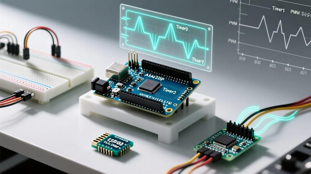
The standard Arduino Uno (and Nano) relies on the ATmega328P microcontroller, which features three internal timers (Timer0, Timer1, and Timer2) mapped to six specific pins: 3, 5, 6, 9, 10, and 11. By default, the Arduino core configures these timers to output an 8-bit resolution (0-255 duty cycle) at roughly 490 Hz, with pins 5 and 6 operating at 980 Hz.
The Hidden Timer Conflicts
The most critical failure mode for beginners using native PWM is timer collision. According to the official Arduino analogWrite documentation, modifying timer frequencies to achieve higher resolution or ultrasonic outputs will break core Arduino functions. For example:
- Timer0 (Pins 5, 6): Changing the prescaler on Timer0 will instantly break
millis(),delay(), anddelayMicroseconds(). - Timer1 (Pins 9, 10): The widely used
Servo.hlibrary hijacks Timer1 to generate its 50Hz pulse train. If you attempt to useanalogWrite()on pins 9 or 10 while servos are attached, the PWM output will fail or cause servo jitter.
The I2C Powerhouse: NXP PCA9685
When your project requires more than six channels, the NXP PCA9685 is the undisputed industry standard. Originally designed for automotive RGB backlighting, this 16-channel, 12-bit PWM driver communicates via the I2C bus, freeing your microcontroller's CPU from generating software-based pulse trains.
Component Variants and 2026 Pricing
You will typically encounter the PCA9685 in two breakout board formats:
- Adafruit 16-Channel PWM/Servo Shield (Official): Priced around $14.99. Features onboard 5V regulation, a massive 2200µF electrolytic capacitor for servo brownout protection, and terminal blocks. Ideal for plug-and-play robotics.
- Generic Clone Modules (Blue/Red PCBs): Priced between $2.50 and $4.00 on bulk marketplaces. These lack the large capacitor and often ship with marginal I2C pull-up resistors (frequently 10kΩ instead of the optimal 4.7kΩ), requiring hardware modifications for long wire runs.
Head-to-Head Comparison Matrix
| Feature | Native ATmega328P | PCA9685 (I2C) | TLC5940 (SPI/Bitbang) |
|---|---|---|---|
| Channel Count | 6 | 16 (Addressable up to 62) | 16 (Daisy-chainable) |
| Resolution | 8-bit (256 steps) | 12-bit (4096 steps) | 12-bit (4096 steps) |
| Max Frequency | ~31.25 kHz (custom) | 1526 Hz (default 200Hz) | Depends on SPI clock |
| Output Type | Voltage Source (5V) | Open-Drain / Totem-Pole | Constant Current Sink |
| CPU Overhead | Zero (Hardware handled) | Near Zero (I2C updates) | High (Requires SPI/Bitbang) |
| Best Use Case | Simple DC motors, 1-2 servos | Multi-servo robotics, high-res LEDs | High-power LED matrices, displays |
Real-World Failure Modes and Edge Cases
Reading a datasheet is easy; debugging a noisy breadboard at 2 AM is hard. Here are the specific edge cases you must engineer around when integrating external PWM peripherals.
1. PCA9685 I2C Bus Capacitance and Signal Degradation
The I2C specification limits bus capacitance to 400pF. When wiring a PCA9685 to an Arduino using ribbon cables longer than 30cm, the parasitic capacitance of the wires will round off the square edges of the I2C clock signal, leading to missed ACK bits and frozen servos. The Fix: Always install 4.7kΩ pull-up resistors on both SDA and SCL lines near the microcontroller, and keep I2C traces under 15cm when operating at 400kHz Fast Mode.
2. TLC5940 Constant Current Sink Confusion
Unlike the PCA9685 which outputs a voltage, the TI TLC5940 is a constant-current sink. You cannot wire a standard hobby servo directly to a TLC5940. It is strictly designed for driving LEDs where you set a global current limit via a single IREF resistor (e.g., a 2kΩ resistor yields ~10mA per channel). Attempting to drive inductive loads like motors or servos without external N-channel MOSFETs will destroy the IC.
3. Ground Loops in High-Current LED Arrays
When using a PCA9685 to switch high-current 12V LED strips via external MOSFETs, the sudden inrush current can cause the ground potential to bounce. If the Arduino and the PCA9685 share a thin ground wire back to the power supply, the logic ground will spike, resetting the ATmega328P. Always use a star-ground topology, routing high-current grounds directly to the power supply, and tying logic grounds together at a single point.
Step-by-Step: Wiring PCA9685 for High-Current Loads
The PCA9685's onboard MOSFETs are rated for roughly 25mA per channel. To drive a 5A, 12V LED strip, you must use the PWM signal to switch an external Logic-Level N-Channel MOSFET (like the IRLZ44N).
- Power Separation: Connect the PCA9685
VCCpin to the Arduino 5V (for I2C logic). Connect the green terminal blockV+to your 12V LED power supply. - Gate Protection: Wire the PCA9685 PWM output pin to the MOSFET Gate through a 100Ω resistor. This limits inrush current into the gate capacitance, protecting the PCA9685's internal driver.
- Pull-Down Resistor: Wire a 10kΩ resistor between the MOSFET Gate and Ground. This ensures the MOSFET stays off during Arduino boot-up when I2C pins are floating.
- Inductive Kickback: If driving a DC motor or solenoid instead of LEDs, place a 1N4007 flyback diode in reverse parallel across the load terminals to absorb voltage spikes when the magnetic field collapses.
Expert Tip for ESP32 Users: If you are migrating from the Arduino Uno to an ESP32 in 2026, note that the ESP32 features a dedicated LED Control (LEDC) peripheral capable of 16-channel, 20-bit hardware PWM natively. Before buying a PCA9685, verify if your ESP32's native LEDC pins can satisfy your routing constraints.
Frequently Asked Questions
Can I change the frequency of the Arduino PCA9685?
Yes. The PCA9685 operates on an internal 25MHz oscillator. By writing to the PRE_SCALE register via I2C, you can adjust the frequency from 24Hz up to 1526Hz. For standard RC servos, keep it at 50Hz. For LED dimming to avoid camera flicker, push it to 1000Hz or higher.
Why is my servo twitching when using the PCA9685?
Servo jitter on I2C drivers is almost always a power delivery issue. Servos draw peak current (up to 2A per servo) during stall or rapid acceleration. If your V+ power supply sags below 4.5V, the PCA9685's internal logic resets, sending erratic pulses. Solder a 1000µF low-ESR electrolytic capacitor directly across the V+ and GND terminal blocks on the breakout board.
How many PCA9685 boards can I chain together?
The board features 6 address jumpers (A0 to A5), allowing for 62 unique I2C addresses (0x40 to 0x7E). This theoretically supports 992 individual PWM channels on a single Arduino I2C bus, provided you use an I2C multiplexer like the TCA9548A to manage bus capacitance limits.