
Choosing the Right Ultrasonic Sensor for Your Arduino
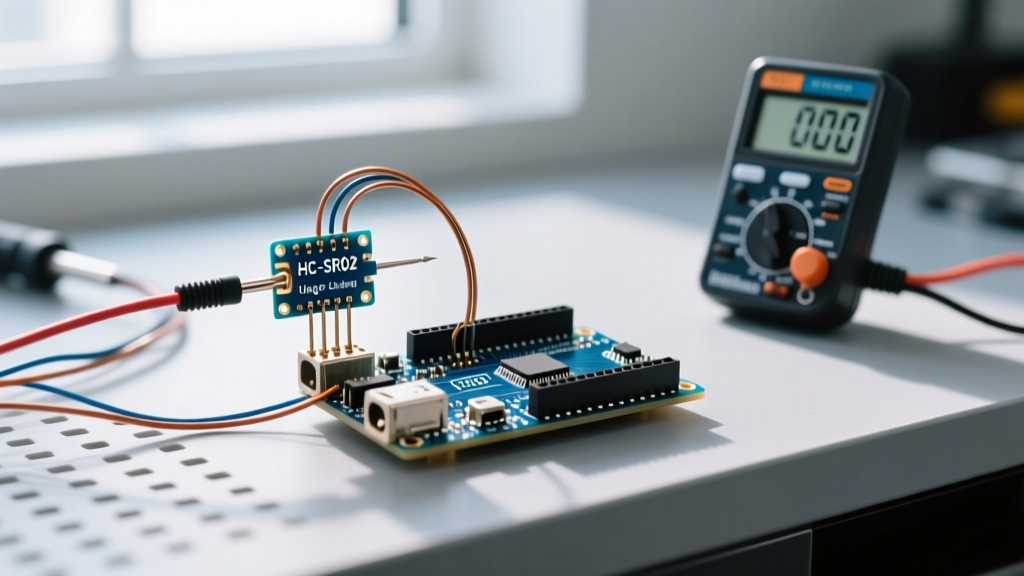
When building an ultrasonic sensor Arduino project, the ubiquitous HC-SR04 is usually the first module beginners reach for. Priced between $1.50 and $3.00 in 2026, it offers a 2cm to 400cm range with roughly 3mm accuracy. However, it is not always the right tool. If your project involves outdoor environments, high humidity, or dust, the standard open-mesh transducers of the HC-SR04 will quickly degrade or false-trigger. Selecting the correct hardware is the first step toward a reliable embedded system.
| Model | Range | Blind Spot | Environment | Avg Price (2026) |
|---|---|---|---|---|
| HC-SR04 | 2cm - 400cm | ~20mm | Indoor / Dry | $1.50 - $3.00 |
| JSN-SR04T | 20cm - 600cm | ~200mm | Outdoor / Wet | $6.00 - $9.00 |
| RCWL-1601 | 2cm - 500cm | ~20mm | Indoor / 3.3V Native | $2.50 - $4.00 |
Understanding the Blind Spot
Every ultrasonic transducer has a physical blind spot caused by the ringing effect of the piezoelectric crystal. After emitting a 40kHz burst, the transmitter cone continues to vibrate for a few milliseconds. The receiver cannot distinguish between this residual vibration and an actual echo. For the standard HC-SR04, this blind spot is approximately 20mm. If your application requires measuring distances shorter than 2cm, you must switch to an infrared Time-of-Flight (ToF) sensor like the VL53L0X instead.
Wiring and the 3.3V Logic Level Trap
The most common point of failure for beginners occurs when migrating from a 5V Arduino Uno to a 3.3V microcontroller like the ESP32, Raspberry Pi Pico (RP2040), or Arduino Nano 33 IoT. The HC-SR04 is powered by 5V and outputs a 5V HIGH signal on its Echo pin. Feeding a 5V signal directly into a 3.3V GPIO pin will permanently damage the microcontroller's silicon.
To safely interface a 5V ultrasonic sensor Arduino module with a 3.3V logic board, you must use a voltage divider or a dedicated logic level shifter. A simple voltage divider using a 1kΩ and 2kΩ resistor network will drop the 5V Echo signal down to a safe ~3.33V. For high-speed or multi-sensor arrays, a bidirectional logic level converter utilizing the BSS138 MOSFET (such as the SparkFun Logic Level Converter) is highly recommended to preserve signal edge integrity. For a deeper dive into voltage thresholds, refer to the SparkFun Logic Level Tutorial.
The Physics: Why Temperature Compensation Matters
Ultrasonic sensors do not measure distance directly; they measure time. The module calculates distance by timing how long it takes for a 40kHz acoustic wave to travel to an object and bounce back. Because the speed of sound in air is heavily dependent on temperature, ignoring thermal drift will introduce significant measurement errors.
The Speed of Sound Formula:
v = 331.3 * √(1 + T/273.15)
Where v is velocity in m/s and T is temperature in Celsius.
At 20°C, sound travels at 343.21 m/s (or 0.034321 cm/µs). However, if your sensor is deployed in an unheated garage at 0°C, the speed drops to 331.3 m/s. Over a 3-meter distance, this temperature differential introduces an error of nearly 11 centimeters. For precision applications, integrate a digital temperature sensor like the BME280 and dynamically adjust your distance multiplier in the firmware. You can verify the underlying thermodynamic principles via Georgia State University HyperPhysics.
Writing the Code: Raw pulseIn vs. Library Abstractions
To trigger the HC-SR04, the Arduino must pull the Trigger pin HIGH for exactly 10 microseconds. The module then emits an 8-cycle sonic burst and pulls the Echo pin HIGH until the sound wave returns. We measure this duration using the pulseIn() function. According to the Arduino pulseIn Reference, it is critical to set a timeout parameter to prevent your main loop from hanging indefinitely if an echo is never received.
Optimized Arduino Implementation
const int trigPin = 9;
const int echoPin = 10;
const float tempC = 22.0; // Update dynamically if using a temp sensor

void setup() {
  pinMode(trigPin, OUTPUT);
  pinMode(echoPin, INPUT);
  Serial.begin(115200);
}

void loop() {
  digitalWrite(trigPin, LOW);
  delayMicroseconds(2);
  digitalWrite(trigPin, HIGH);
  delayMicroseconds(10);
  digitalWrite(trigPin, LOW);

  // Timeout set to 30000µs (approx 5 meters max)
  long duration = pulseIn(echoPin, HIGH, 30000);

  float speedOfSound = 331.3 * sqrt(1 + (tempC / 273.15));
  float cmPerMicrosecond = speedOfSound / 10000.0;

  float distance = (duration * cmPerMicrosecond) / 2.0;

  if (duration == 0) {
    Serial.println("Out of range or timeout");
  } else {
    Serial.print("Distance: ");
    Serial.print(distance);
    Serial.println(" cm");
  }
  delay(50);
}
Real-World Troubleshooting and Edge Cases
Even with perfect wiring and temperature-compensated code, ultrasonic sensors are subject to the physical limitations of acoustic waves. Understanding these edge cases separates hobbyists from professional embedded engineers.
Target Material Absorption
Ultrasonic sensors rely on specular reflection. Hard, flat surfaces like wood, plastic, and metal reflect 40kHz waves beautifully. However, soft, porous materials like cotton, foam, and heavy curtains absorb acoustic energy. If your robot is navigating toward a bed or a sofa, the HC-SR04 may fail to register an echo, resulting in a collision. Always pair ultrasonic sensors with a secondary sensing modality, such as infrared or LiDAR, when operating in environments with soft furnishings.
The 15-Degree Beam Angle Cone
The HC-SR04 does not emit a laser-like beam; it projects a conical wave with an effective beam angle of roughly 15 to 30 degrees. If an object is positioned at the extreme edge of this cone, the acoustic wave may glance off the surface at an angle rather than reflecting directly back to the receiver. This is known as acoustic glancing. To mitigate this, ensure your target objects are wider than the beam cone at the maximum detection distance, or mount multiple sensors at overlapping angles.
Acoustic Crosstalk in Multi-Sensor Arrays
If you are building a robotic vehicle with four HC-SR04 modules for 360-degree obstacle avoidance, you cannot trigger them simultaneously. If all four sensors emit a 40kHz burst at the exact same millisecond, Sensor A's receiver will detect the echo from Sensor B's transmitter, resulting in wildly inaccurate phantom readings. This phenomenon is called acoustic crosstalk.
- Solution 1 (Sequential Polling): Trigger each sensor one by one, waiting at least 25ms between each trigger to allow the longest possible echo to return and the acoustic ringing to dissipate.
- Solution 2 (Hardware Encoding): Use modules that support frequency modulation or digital encoding, though these are significantly more expensive and rare in the hobbyist market.
By respecting the physical limitations of sound, properly shifting your logic levels, and compensating for thermal drift, your ultrasonic sensor Arduino integration will achieve industrial-level reliability in your DIY projects.