
Decoding the Anatomy of an Infrared Distance Sensor Arduino Setup
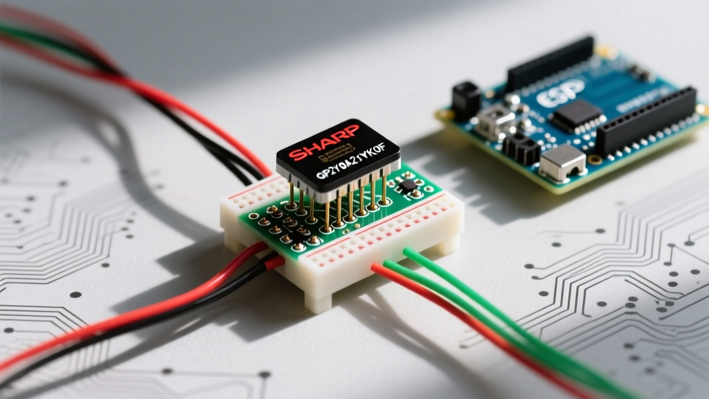
When developers search for an infrared distance sensor Arduino tutorial, they are almost universally directed to the Sharp GP2Y0A21YK0F. Despite the proliferation of modern Time-of-Flight (ToF) modules in 2026, this analog IR sensor remains a staple in robotics and DIY automation due to its low $3.50 to $5.00 price point and simple ADC interface. However, treating this sensor as a simple 'plug-and-play' analog component is a critical mistake. The official datasheet reveals complex non-linear behaviors, strict power conditioning requirements, and optical blind spots that can derail a project if ignored.
In this datasheet explainer, we dissect the technical specifications of the GP2Y0A21YK0F, translating its optical graphs and electrical characteristics into actionable engineering constraints for your microcontroller projects.
Datasheet Quick Reference: Sharp GP2Y0A21YK0F
- Measurement Range: 10 cm to 80 cm
- Output Type: Analog Voltage (Inverse to distance)
- Operating Voltage: 4.5V to 5.5V
- Average Current Draw: 30 mA
- Peak Current Draw: 200 mA (during LED pulse)
- Update Period: 38 ms (approx. 26 Hz)
The Inverse Voltage Curve and PSD Technology
Unlike ultrasonic sensors that output a timed digital pulse, the GP2Y0A21YK0F relies on a Position Sensitive Detector (PSD). The sensor emits an 850nm infrared beam. When this beam hits an object, the reflected light strikes the PSD array. The physical location where the light hits the PSD changes based on the angle of reflection, which correlates directly to the object's distance.
The most critical takeaway from the Sharp GP2Y0A21YK0F Datasheet is the Output Voltage vs. Distance graph. The relationship is highly non-linear and inverse. At 10 cm, the output peaks at roughly 3.1V. As the distance increases to 80 cm, the voltage drops asymptotically toward 0.4V. This means the sensor's resolution is heavily skewed: it is highly sensitive to distance changes at close range (10-20 cm) but suffers from poor resolution at the far end (60-80 cm), where a 10 cm physical shift might only yield a 0.05V change.
The 0-10 cm Blind Spot Edge Case
A frequently overlooked datasheet detail is the behavior inside the 0 to 10 cm range. Because of the physical offset between the IR emitter and the PSD receiver lens, objects closer than 10 cm cause the reflection angle to miss the active PSD area. Consequently, the output voltage violently drops. An object placed at 2 cm might output the exact same voltage as an object placed at 35 cm. If your robot uses this sensor for collision avoidance, a failure to programmatically guard against the blind spot will result in the robot driving straight into walls, falsely interpreting the low voltage as 'clear path'.
Power Dynamics: The Mandatory 10µF Capacitor Rule
The electrical characteristics section of the datasheet specifies an average current consumption of 30 mA. However, this is an average. The internal IR LED is pulsed at high intensity to maximize the signal-to-noise ratio against ambient sunlight. During these microsecond pulses, the current draw spikes to 200 mA.
If you power the sensor directly from the 5V pin of an Arduino Nano or an ESP32 development board without local energy storage, these 200 mA spikes will cause localized voltage sags (brownouts). This manifests as erratic analog readings or microcontroller resets. The datasheet explicitly mandates a bypass capacitor.
| Wire Color | Pin Function | Microcontroller Connection | Engineering Notes |
|---|---|---|---|
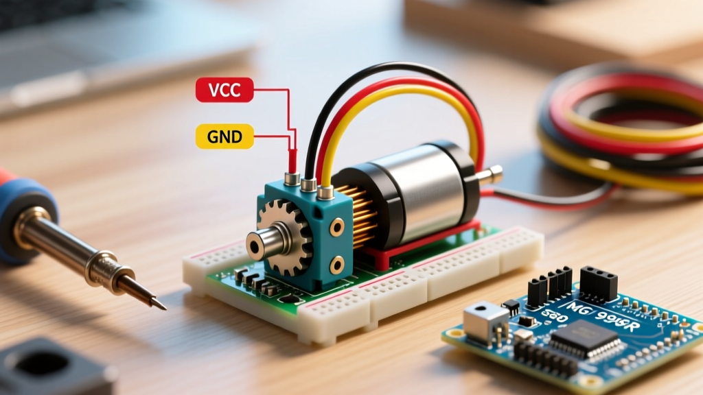
| Red | VCC | 5V (Do not use 3.3V) | Requires 4.5V minimum. Use a dedicated 5V rail if possible. |
| Black | GND | GND | Must share a common ground with the MCU for accurate ADC. |
| Yellow/White | VOUT | Analog Input (e.g., A0) | Output impedance is roughly 200 ohms; easily driven into ADC. |
Actionable Fix: Solder a 10µF to 47µF electrolytic capacitor directly across the VCC and GND wires, as physically close to the sensor housing as possible. This local reservoir supplies the 200 mA peak current, keeping the 5V rail stable. For a comprehensive look at stable sensor power delivery, refer to the Pololu GP2Y0A21YK0F Integration Guide.
Translating Analog Readings to Centimeters in C++
Because the output curve is non-linear, a simple linear map function will fail. The standard Arduino analogRead() returns a 10-bit integer (0-1023). First, convert this to voltage, then apply a regression formula.
A common mathematical approximation derived from the datasheet's curve is:
Distance (cm) = 123432 * pow(Voltage, -1.15)
However, using the pow() function in C++ on an 8-bit ATmega328P (Arduino Uno/Nano) is computationally expensive, taking hundreds of microseconds per calculation and bloating the compiled binary size. For real-time robotics in 2026, a piecewise linear approximation or a pre-calculated lookup table (LUT) stored in PROGMEM is vastly superior.
Optimized C++ Lookup Strategy
Instead of floating-point math, sample the voltage, divide it into discrete 0.1V bins, and return the corresponding distance from an array. This reduces the processing overhead from hundreds of microseconds to mere nanoseconds, freeing up your MCU's main loop for motor control and PID calculations.
Environmental Failure Modes: Reflectivity and Sunlight
The datasheet's test conditions assume a target with 90% diffuse reflectivity (pure matte white). In real-world deployments, material properties drastically alter the PSD's received light intensity.
- Low Albedo Targets: Black rubber or dark fabrics absorb 850nm IR light. A black object at 30 cm may reflect the same amount of light as a white object at 70 cm, causing the sensor to overestimate the distance.
- Specular Reflections: Glass, polished metal, or glossy tiles will reflect the IR beam away from the PSD receiver (mirror effect), resulting in infinite distance readings (0.4V) even when an object is directly in front of the lens.
- Optical Saturation: Direct sunlight contains massive amounts of 850nm infrared radiation. While the sensor's internal optical filter and modulated pulsing help reject ambient light, pointing the sensor directly at the sun or under high-intensity halogen shop lights will saturate the PSD, pegging the output to maximum voltage regardless of obstacles.
2026 Comparison Matrix: Sharp IR vs. Modern Alternatives
Is the GP2Y0A21YK0F still the right choice for your project today? Compare its datasheet specs against modern alternatives to make an informed BOM (Bill of Materials) decision.
| Feature | Sharp GP2Y0A21YK0F | Sharp GP2Y0A02YK0F | ST VL53L1X (ToF) |
|---|---|---|---|
| Technology | IR Triangulation (PSD) | IR Triangulation (PSD) | VCSEL Time-of-Flight |
| Range | 10 - 80 cm | 20 - 150 cm | 4 cm - 400 cm |
| Output Interface | Analog Voltage | Analog Voltage | I2C Digital |
| Blind Spot | 0 - 10 cm | 0 - 20 cm | None (Accurate down to 4cm) |
| Sunlight Immunity | Moderate | Moderate | Excellent (IR Pass Filters) |
| Approx. Cost (2026) | $4.00 | $6.50 | $7.50 |
Summary and Final Integration Advice
The Sharp GP2Y0A21YK0F remains a highly viable, cost-effective infrared distance sensor Arduino makers can leverage for edge detection, line-following, and basic proximity alerts. By respecting the datasheet's mandates—specifically the 10µF bypass capacitor, the 10 cm blind spot, and the non-linear voltage curve—you can extract reliable, repeatable data. However, if your 2026 project requires millimeter precision, operation under direct sunlight, or detection of highly specular surfaces, bypass analog triangulation entirely and allocate the extra $3.50 for an I2C Time-of-Flight sensor.