
Beyond Basic Analog Reads: Engineering Reliable Water Level Drivers
Interfacing a water level sensor Arduino setup is often introduced as a beginner project using a simple resistive probe and a basic analogRead() function. However, in real-world 2026 deployments—ranging from automated hydroponics to sump pump fail-safes—naive DC-driven resistive sensing fails rapidly. Electrolysis destroys probe traces, and surface ripples introduce severe ADC jitter. This guide moves past basic tutorials, providing a professional library and driver architecture for robust fluid monitoring using modern microcontrollers like the Arduino Uno R4 and ESP32.
Sensor Topology Comparison Matrix
Before writing driver code, selecting the correct physical transducer is critical. The market offers three primary topologies, each requiring a different software approach.
| Sensor Type | Common Model | Approx. Cost (2026) | Interface | Lifespan in Continuous Submersion |
|---|---|---|---|---|
| Resistive (Bare PCB) | YL-69 / FC-37 | $2.50 | Analog (Voltage Divider) | < 72 hours (DC) / 1+ year (AC) |
| Capacitive (Non-Contact) | XKC-Y25-V / DFRobot SEN0205 | $15.00 - $18.00 | Digital PWM / I2C | Indefinite (Isolated) |
| Ultrasonic (Top-Down) | JSN-SR04T | $12.00 | Digital Pulse Width | Years (Keep transducer dry) |
The Galvanic Corrosion Problem (And the AC Excitation Fix)
The most common failure mode in DIY fluid monitoring is galvanic corrosion and electrolysis. When you apply a continuous 5V or 3.3V DC signal across a submerged resistive probe (like the YL-69), the water acts as an electrolyte. The anode trace rapidly oxidizes and dissolves into the fluid, leaving you with an open circuit and contaminated water.
Expert Rule of Thumb: Never drive a submerged resistive sensor with a continuous DC voltage. If your application requires continuous monitoring, you must use an AC excitation signal or switch to a capacitive topology.
Implementing the AC Excitation Driver
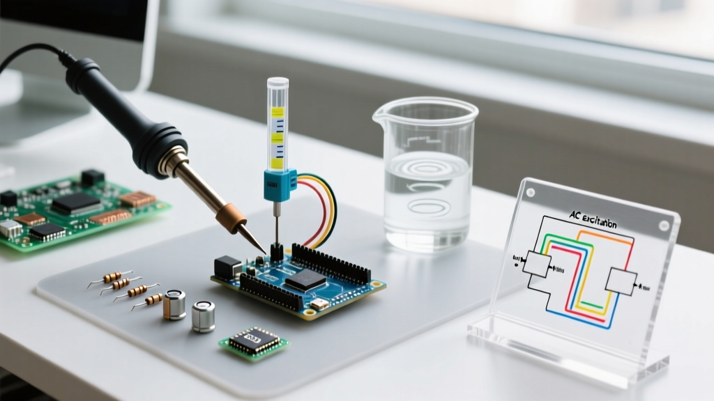
To solve electrolysis, we alternate the current direction using a high-frequency PWM square wave, effectively creating an AC signal. By driving the sensor's VCC pin with a 1kHz PWM signal and reading the analog output only during the HIGH phase, we eliminate net DC ion migration.
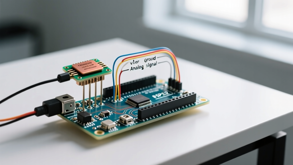
Here is the hardware mapping for an Arduino Uno R4 Minima:
- PWM Drive Pin: D9 (Outputs 1kHz square wave to sensor VCC)
- Analog Read Pin: A0 (Reads voltage divider output)
- Sensor GND: Common ground with Arduino
Signal Conditioning: Filtering Ripple Noise
Water is rarely perfectly still. Pumps, vibrations, and thermal convection create surface ripples. Because resistive and capacitive sensors measure the exact meniscus line, these ripples translate into high-frequency noise on your ADC. According to the Arduino analogRead documentation, standard 10-bit or 12-bit ADCs will fluctuate wildly under these conditions.
Instead of writing complex rolling average algorithms from scratch, we leverage the RunningMedian library (maintained by Rob Tillaart, available via the Arduino Library Manager). A median filter is mathematically superior to a mean filter for fluid dynamics because it completely ignores outlier spikes caused by air bubbles or momentary splashes.
Installing the Required Libraries
Open your Arduino IDE Library Manager and install:
- RunningMedian (for outlier rejection)
- ArduinoFilters (optional, for secondary low-pass IIR filtering)
Complete AC-Excited Driver Code Architecture
Below is a production-ready driver snippet for a resistive water level sensor. It handles the PWM AC excitation, samples the ADC synchronously, and applies a median filter to output a stable percentage.
#include <RunningMedian.h>

// Pin Definitions
const int PWM_DRIVE_PIN = 9;
const int ANALOG_SENSE_PIN = A0;

// Filter Configuration
RunningMedian waterSamples = RunningMedian(15);

// Calibration Constants (Adjust based on your specific fluid conductivity)
const int DRY_THRESHOLD = 50;
const int SUBMERGED_THRESHOLD = 850;

void setup() {
  Serial.begin(115200);

  // Configure PWM for ~1kHz AC excitation to prevent electrolysis
  pinMode(PWM_DRIVE_PIN, OUTPUT);
  analogWrite(PWM_DRIVE_PIN, 128); // 50% duty cycle square wave

  pinMode(ANALOG_SENSE_PIN, INPUT);
}

void loop() {
  int rawADC = readSensorAC();
  waterSamples.add(rawADC);

  // Get the median value to ignore splash outliers
  int stableADC = waterSamples.getMedian();

  // Map ADC to percentage (0% = Dry, 100% = Fully Submerged)
  int waterLevelPercent = map(stableADC, DRY_THRESHOLD, SUBMERGED_THRESHOLD, 0, 100);
  waterLevelPercent = constrain(waterLevelPercent, 0, 100);

  Serial.print("Raw: ");
  Serial.print(stableADC);
  Serial.print(" | Level: ");
  Serial.print(waterLevelPercent);
  Serial.println("%");

  delay(250); // 4Hz sampling rate is sufficient for fluid levels
}

// Synchronous read function
int readSensorAC() {
  // Briefly ensure PWM is stable, then sample
  return analogRead(ANALOG_SENSE_PIN);
}
Integrating Non-Contact Capacitive Sensors (I2C & Digital)
If your application involves potable water, hydroponic nutrients, or corrosive chemicals, resistive probes are unsuitable regardless of AC excitation. In 2026, non-contact capacitive sensors like the XKC-Y25-V or the I2C-based DFRobot SEN0205 are the industry standard for reliable voltage divider and fluid monitoring circuits.
Driver Logic for Capacitive Topologies
Capacitive sensors measure the dielectric constant of the material against the tank wall. Water has a dielectric constant of ~80, while air is ~1. The driver logic shifts from reading analog conductivity to reading digital thresholds or I2C registers.
- Digital Output (XKC-Y25): Requires an interrupt-driven driver. Attach a hardware interrupt to the sensor's signal pin to trigger a 'tank full' event without polling.
- I2C Output (DFRobot SEN0205): Requires the manufacturer's specific I2C library. Ensure your I2C bus has 4.7kΩ pull-up resistors, as the sensor's internal pull-ups are often too weak for long wire runs in humid environments.
Calibration Framework and Edge Cases
A robust driver must account for environmental variables that alter sensor readings. When deploying your water level sensor Arduino project, incorporate the following calibration checks into your setup routine:
1. Fluid Conductivity Variations
Resistive sensors do not measure depth; they measure conductivity. Pure distilled water is an insulator and will read as 'dry' on a YL-69 sensor. Conversely, heavily fertilized hydroponic water will max out the ADC at half-submersion. Actionable fix: Implement a two-point calibration function in your code that records the ADC value at 10% and 90% tank capacity during initial setup, storing these values in the microcontroller's EEPROM.
2. Mineral Buildup (Scaling)
Over months of operation, calcium and magnesium carbonate will precipitate onto resistive probes, creating a permanent conductive bridge that causes 'ghost' readings even when the tank is empty. If your dry-state baseline creeps up by more than 15% over a week, trigger a maintenance alert via your serial or IoT dashboard.
3. Temperature Drift
The conductivity of water increases by approximately 2% per degree Celsius. If your tank experiences wide thermal swings (e.g., an outdoor rain barrel), integrate a DS18B20 temperature sensor and apply a linear compensation multiplier to your final mapped percentage.
Summary
Building a reliable water level sensor Arduino system requires moving beyond simple analog reads. By implementing AC excitation to halt galvanic corrosion, utilizing the RunningMedian library to filter hydrodynamic noise, and selecting the appropriate capacitive topology for sensitive fluids, you transform a fragile hobbyist circuit into a robust, industrial-grade monitoring solution.