
The Ultimate Weight Sensor Arduino Integration Guide
Building a custom digital scale, a hopper level monitor, or a force-feedback robotics rig requires precise mass measurement. When tackling a weight sensor Arduino project, the undisputed industry standard for hobbyists and prototyping engineers is the combination of a strain gauge load cell and the HX711 24-bit analog-to-digital converter (ADC). While the Arduino Uno R4 Minima and ESP32-S3 boards of 2026 boast impressive internal ADCs, they lack the programmable gain amplification (PGA) required to read the microvolt-level differential signals generated by load cells.
This guide bypasses the fluff and dives straight into the electrical engineering principles, exact wiring topologies, and C++ calibration routines needed to achieve sub-gram accuracy. We will also cover a critical hardware modification to increase your sampling rate from 10 SPS to 80 SPS—a trick rarely documented in beginner tutorials.
Bill of Materials & 2026 Pricing
Before wiring, ensure you have the correct components. Prices reflect typical Q1 2026 market rates from major distributors like SparkFun, Adafruit, and reputable Amazon vendors.
| Component | Model / Specification | Approx. Cost | Notes |
|---|---|---|---|
| Microcontroller | Arduino Uno R4 Minima | $20.00 | 5V logic, ideal for standard HX711 modules. |
| Load Cell | CZL601 50kg Straight-Bar | $9.50 | Aluminum alloy, 2.0mV/V sensitivity. |
| ADC Amplifier | HX711 Breakout Board | $2.50 | Ensure it includes the shielding can over the IC. |
| Wiring | 24 AWG Stranded Copper | $5.00/spool | Stranded wire prevents microphonic noise artifacts. |
Understanding the Wheatstone Bridge Physics
To troubleshoot effectively, you must understand what the HX711 is actually measuring. A standard 4-wire load cell contains four strain gauges arranged in a Wheatstone bridge configuration. When force is applied, the metal substrate deforms, altering the electrical resistance of the gauges.
Expert Insight: A typical 50kg load cell excited at 5V will only output a maximum differential voltage of 10mV (2.0mV/V) at full capacity. The Arduino's internal 14-bit ADC on the R4 has a resolution of roughly 0.3mV per step—far too coarse for precision weighing. The HX711's 24-bit resolution and 128x PGA gain amplify this tiny signal into a robust digital stream.
Step-by-Step Wiring Topology
Improper wiring is the leading cause of erratic readings and blown HX711 ICs. Pay strict attention to the excitation voltage and logic levels.
1. Load Cell to HX711 (Analog Side)
The CZL601 load cell typically features four color-coded wires. Solder these directly to the E+, E-, A+, A- pads on the HX711. Do not use breadboards for this analog connection; the contact resistance of breadboard springs will introduce severe thermal drift.
- Red (Excitation+): Connects to HX711 E+
- Black (Excitation-): Connects to HX711 E-
- White (Signal+): Connects to HX711 A+
- Green (Signal-): Connects to HX711 A-
2. HX711 to Arduino (Digital Side)
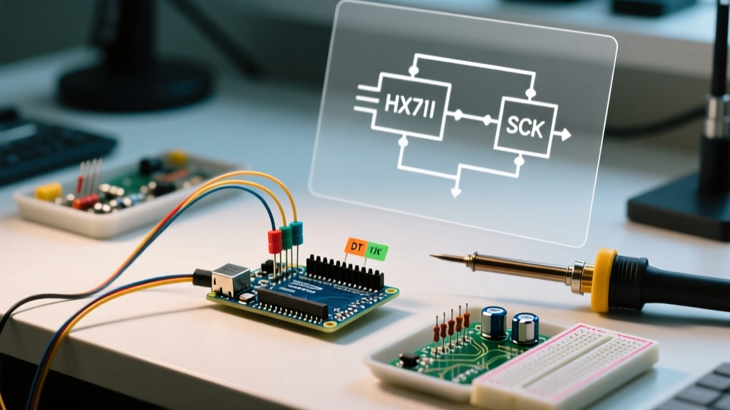
The HX711 communicates via a proprietary serial protocol requiring only two digital pins. You can use the hardware serial pins, but software serial on standard digital pins is preferred to keep the USB serial free for debugging.
| HX711 Pin | Arduino Uno R4 Pin | Function |
|---|---|---|
| VCC | 5V | Powers the IC and provides excitation voltage to the load cell. |
| GND | GND | Common ground reference. |
| DT (Data) | D3 | Serial data output from HX711 to MCU. |
| SCK (Clock) | D2 | Clock signal from MCU to HX711. |
Warning: Never power the HX711 VCC pin with 3.3V if you are using a standard 5V Arduino. The IC will operate, but the load cell excitation voltage will drop, halving your signal-to-noise ratio. Conversely, if using an ESP32, you must use a logic level shifter on the SCK and DT pins, as the HX711 outputs 5V logic which will fry the ESP32's 3.3V GPIOs.
C++ Calibration and Weighing Code
We utilize the industry-standard HX711 library by Bogdan Necula. Install this via the Arduino Library Manager before proceeding.
Phase 1: Finding the Calibration Factor
Every load cell has a unique sensitivity variance. You must calculate a custom calibration factor. Upload the following sketch, open the Arduino IDE Serial Monitor at 9600 baud, and place a known mass (e.g., a 1kg dumbbell) on the scale.
#include <HX711.h>

HX711 scale;
const int LOADCELL_DOUT_PIN = 3;
const int LOADCELL_SCK_PIN = 2;

void setup() {
  Serial.begin(9600);
  scale.begin(LOADCELL_DOUT_PIN, LOADCELL_SCK_PIN);

  // Tare the scale to zero with no load
  scale.tare();

  // Set a temporary initial scale factor
  scale.set_scale(2280.f);
  Serial.println("Place a known weight on the scale now...");
  delay(5000);

  // Read the raw average
  long raw_reading = scale.get_units(10);
  Serial.print("Raw reading: ");
  Serial.println(raw_reading);
  Serial.println("Divide the raw reading by your known weight in grams to get your calibration factor.");
}

void loop() {
  // Empty loop for calibration phase
}
The Math: If your 1000g weight yields a raw reading of 425,000, your calibration factor is 425000 / 1000 = 425.0.
Phase 2: Production Weighing Code
Once you have your factor, implement the final production code. This snippet includes a moving average filter and automatic tare verification.
#include <HX711.h>

HX711 scale;
const int LOADCELL_DOUT_PIN = 3;
const int LOADCELL_SCK_PIN = 2;
const float CALIBRATION_FACTOR = 425.0; // Replace with your value

void setup() {
  Serial.begin(115200);
  scale.begin(LOADCELL_DOUT_PIN, LOADCELL_SCK_PIN);
  scale.set_scale(CALIBRATION_FACTOR);
  scale.tare(); // Reset to 0g on boot
}

void loop() {
  if (scale.is_ready()) {
    // get_units(5) takes 5 readings and averages them to reduce noise
    float weight = scale.get_units(5);

    Serial.print("Mass: ");
    Serial.print(weight, 2); // Print to 2 decimal places
    Serial.println(" g");
  } else {
    Serial.println("HX711 not found or busy.");
  }
  delay(100);
}
Advanced Hardware Hack: Pushing 80 SPS
By default, the HX711 samples at 10 Samples Per Second (SPS). For fast-moving conveyor belts or dynamic force testing, this is insufficient. The HX711 IC features a RATE pin (Pin 15 on the bare IC).
- Pin 15 LOW (Default): 10 SPS, 50Hz noise rejection.
- Pin 15 HIGH: 80 SPS, 60Hz noise rejection.
How to mod: On most red or green breakout boards, locate the tiny pad labeled RATE near the IC. Using a fine-tip soldering iron (like a Weller RT1), bridge the RATE pad to the adjacent VCC pad with a microscopic dab of solder. Your library code requires zero changes, but your scale.is_ready() loop will now trigger 8 times faster, drastically improving the responsiveness of your weight sensor Arduino setup.
Troubleshooting Matrix: Edge Cases & Failures
When your readings fail, use this diagnostic matrix to isolate the fault.
| Symptom | Probable Root Cause | Engineering Solution |
|---|---|---|
| Readings drift upward steadily over 10 minutes. | Thermal expansion of the load cell substrate or breadboard contact resistance. | Solder all analog connections. Allow the HX711 to thermally stabilize for 5 minutes before executing tare(). |
| Values jump erratically by ±5g. | Electromagnetic Interference (EMI) from nearby switching power supplies or unshielded wires. | Use shielded 4-wire cable for the load cell. Ground the shield at the HX711 GND pin only (prevent ground loops). |
| Serial Monitor outputs all 0s or hangs. | Clock pin mismatch or HX711 is stuck in sleep mode. | Ensure SCK pin is LOW when idle. If SCK is held HIGH for >60µs, the IC enters power-down. Toggle the pin LOW to wake it. |
| Readings max out at 8388607. | Signal saturation (Gain too high or load cell wired backwards). | Swap A+ and A- wires. Alternatively, switch to Channel B (Gain 32) via the library if measuring very heavy loads. |
Frequently Asked Questions
Can I use multiple load cells with a single Arduino?
Yes. You can wire up to four HX711 modules to a single Arduino by sharing the SCK (Clock) pin but using individual DT (Data) pins for each amplifier. In your C++ code, instantiate multiple HX711 objects and read them sequentially. For a true 4-corner truck scale setup, use a combinator board to wire four half-bridge load cells into a single full Wheatstone bridge, feeding into one HX711.
Does the physical mounting of the load cell affect accuracy?
Absolutely. The CZL601 straight-bar load cell requires a specific mechanical boundary condition. The mounting surface must be perfectly rigid. If the base flexes, the strain gauges will measure the deformation of your project enclosure rather than the applied mass. Always use steel standoffs and ensure the load is applied strictly perpendicular to the center of the beam.