
Beyond the Breadboard: Real-World LCD Integration
Most online tutorials for connecting an LCD screen for Arduino stop at the breadboard phase. They show a tangle of Dupont jumper wires and a basic 'Hello World' sketch, completely ignoring the realities of physical deployment. When you transition from a desk prototype to a real-world IoT enclosure—whether it is a greenhouse climate controller, an outdoor weather station, or an industrial machine dashboard—the rules change dramatically. Signal integrity, environmental hardening, and mechanical stress become the primary points of failure.
In 2026, while high-resolution OLEDs and e-ink displays have gained traction, the classic character LCD (based on the HD44780 controller) and modern TFT shields remain the workhorses of embedded telemetry. They are cost-effective, easily readable in varied lighting, and require minimal processing overhead. However, deploying them in sealed enclosures requires a rigorous approach to electrical and mechanical engineering. This guide bridges the gap between hobbyist wiring and professional peripheral integration.
Hardware Selection Matrix for Field Deployments
Choosing the correct display module depends on your data density requirements, environmental exposure, and budget. Below is a comparison of the most common modules used in professional maker and light-industrial applications today.
| Display Type | Controller / Driver | Typical 2026 Cost | Best Use Case | Real-World Limitation |
|---|---|---|---|---|
| 16x2 Character I2C | HD44780 + PCF8574 | $4.00 - $6.50 | Simple telemetry, single-sensor readouts | Limited data density; poor viewing angles |
| 20x4 Character I2C | HD44780 + PCF8574 | $8.00 - $12.00 | Multi-sensor dashboards, status menus | Backlight draws up to 120mA; requires robust 5V rail |
| 2.4" TFT LCD Shield | ILI9341 (SPI) | $16.00 - $22.00 | Graphical UI, trend charts, touch inputs | High pin count; SPI bus routing complexity |
| Serial OLED (20x4) | US2066 (I2C/SPI) | $28.00 - $35.00 | Extreme temperature environments, high contrast | Premium cost; susceptible to burn-in on static menus |
Electrical Hardening: Solving I2C Bus Capacitance
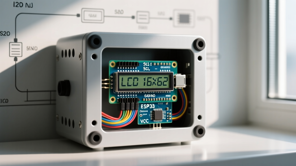
The most common point of failure when integrating an LCD screen for Arduino inside a large enclosure is I2C bus degradation. Standard character LCDs use an I2C backpack (usually based on the PCF8574 or PCF8574A I/O expander). In a breadboard setup, the wires are short, and bus capacitance is negligible. In a real-world enclosure, you might need 40cm to 80cm of cable to route from the microcontroller to the display bezel.
According to the official NXP I2C Specification, the maximum allowable bus capacitance is 400pF. Long, unshielded ribbon cables easily exceed this threshold, resulting in rounded signal edges, corrupted bytes, and a frozen LCD screen.
The Pull-Up Resistor Rule
To combat capacitance in extended I2C runs, you must lower the resistance of your pull-up resistors. Most cheap LCD backpacks come with 4.7kΩ or 10kΩ surface-mount pull-ups. If your cable run exceeds 30cm, you must desolder these and replace them with 2.2kΩ or even 1.8kΩ resistors. This provides a stronger current to charge the parasitic capacitance of the cable, restoring the sharp rising edges required for reliable 100kHz or 400kHz I2C communication.
Connector Selection: Banish Dupont Wires
Never use Dupont jumper wires in a permanent enclosure. Vibration and thermal cycling will cause them to back out of the header pins, leading to intermittent I2C disconnects that can crash your Arduino's Wire library. Instead, use JST-XH 2.54mm connectors with crimped terminals. They feature a positive locking mechanism that withstands industrial vibration profiles.
Environmental Constraints: Temperature and UV Limits
Standard HD44780 LCD modules utilize nematic liquid crystals, which are highly sensitive to environmental extremes. If your enclosure is deployed outdoors, you must account for thermal limits.
- Standard Commercial Grade (0°C to 50°C): Below 0°C, the liquid crystal fluid becomes viscous, causing character updates to smear or lag by several seconds. Above 50°C, the fluid approaches its clearing point, causing the screen to turn completely black or 'wash out'.
- Extended Industrial Grade (-20°C to 70°C): These modules use specialized fluid mixtures and cost roughly 2.5x more than standard displays ($12-$18 for a 16x2). They are mandatory for unheated outdoor enclosures in northern climates.
Pro-Tip for Cold Environments: If you must use a standard LCD in sub-zero temperatures, wire a small 5V PTC heating element behind the LCD PCB. Use a thermistor to trigger the heater via a MOSFET when the ambient temperature drops below 2°C, keeping the liquid crystals within their optimal viscosity range.
Furthermore, standard LCD polarizers degrade rapidly under direct UV exposure, turning yellow and brittle within a single summer season. For outdoor enclosures, ensure the polycarbonate or acrylic enclosure window features a UV-blocking film, or specify modules with UV-stabilized polarizers.
Mechanical Mounting and Vibration Isolation
The physical construction of a typical 16x2 or 20x4 LCD involves a glass substrate bonded to a PCB via a fragile epoxy strip (often covered by a black silicone blob, known as Chip-on-Board or COB). If the enclosure lid flexes, or if the device is subjected to mechanical shock, this epoxy bond can crack, instantly killing the display.
To prevent this, avoid relying solely on the four corner M3 mounting holes. Instead, design a 3D-printed TPU (Thermoplastic Polyurethane) bezel gasket. The TPU acts as a shock absorber, isolating the LCD glass from the rigid enclosure walls. When securing the PCB to the standoffs, use nylon shoulder washers and M3 silicone O-rings under the screw heads. Tighten the screws to exactly 0.5 Nm of torque—overtightening will warp the PCB and fracture the COB bond.
Software Architecture: Non-Blocking Updates
When deploying an LCD screen for Arduino in a production environment, blocking code is unacceptable. The standard LiquidCrystal_I2C library is notorious for hanging the microcontroller if the I2C bus encounters a fault or if the display is disconnected while powered. A hung I2C bus will freeze your entire IoT node, preventing sensor reads or LoRaWAN transmissions.
For robust deployments, migrate to the hd44780 library by Bill Perry, available via the Arduino Library Manager. This library includes built-in I2C bus timeout handling, auto-detection of I2C addresses, and diagnostic pin outputs. It ensures that if the display fails to acknowledge a byte, the library gracefully aborts the transmission rather than entering an infinite while-loop.
Address Collision Troubleshooting
A frequent real-world headache is I2C address collision. The PCF8574 chip uses address 0x27, while the PCF8574A uses 0x3F. If you are integrating multiple peripherals, you must map your bus carefully. Referencing the Adafruit I2C Address Master List is highly recommended during the schematic design phase to ensure your LCD backpack does not conflict with your BME280 sensor (0x76) or RTC module (0x68).
Summary Checklist for Enclosure Integration
- Replace 4.7kΩ I2C pull-ups with 2.2kΩ for cable runs over 30cm.
- Transition from Dupont wires to locking JST-XH 2.54mm harnesses.
- Verify the LCD fluid temperature rating matches your deployment climate.
- Isolate the LCD PCB using TPU gaskets and silicone O-rings to prevent COB fracture.
- Replace legacy display libraries with fault-tolerant alternatives like
hd44780.
By treating the LCD screen not just as a code output, but as a complex electromechanical peripheral, you drastically increase the mean time between failures (MTBF) of your Arduino-based IoT deployments.