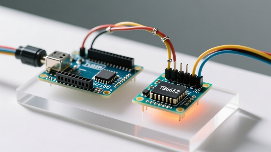

Why Your Arduino Cannot Drive a Motor Directly
A common beginner mistake in robotics is attempting to wire a DC motor directly to an Arduino Uno's digital GPIO pins. The ATmega328P microcontroller at the heart of the Arduino Uno has an absolute maximum current rating of 40mA per pin, with a recommended operating limit of just 20mA. Even a small 6V hobby motor can draw 500mA under normal load and spike past 2A during startup (stall current). Connecting a motor directly to a GPIO pin will instantly destroy the microcontroller's internal silicon due to thermal overload.
Furthermore, DC motors are inductive loads. When power is cut, the collapsing magnetic field generates a reverse voltage spike known as Back-EMF (Electromotive Force). Without a proper Arduino motor interface featuring flyback diodes, this voltage spike will travel back into your microcontroller, causing erratic resets or permanent hardware failure. This is exactly why you need a dedicated motor driver for Arduino projects.
The Showdown: L298N vs TB6612FNG
As of 2026, the hobbyist market is dominated by two primary dual-channel motor driver modules: the classic L298N and the modern TB6612FNG. While both allow you to control the speed and direction of two DC motors simultaneously via PWM and logic pins, their underlying semiconductor architectures dictate vastly different real-world performance profiles.
| Specification | L298N Dual H-Bridge | TB6612FNG MOSFET Driver |
|---|---|---|
| Internal Switching Tech | Bipolar Junction Transistors (BJT) | Metal-Oxide-Semiconductor FETs (MOSFET) |
| Continuous Current per Channel | 2.0A (3.0A peak) | 1.2A (3.2A peak) |
| Voltage Drop (at 1A) | ~2.5V to 3.0V | ~0.5V (R_DS(on) ≈ 0.5Ω) |
| Logic Voltage (VCC) | 5V (Onboard 7805 Regulator) | 2.7V to 5.5V |
| Motor Supply (VM) | 5V to 35V | 2.5V to 13.5V |
| Average Module Price (2026) | $3.00 - $5.00 USD | $5.00 - $8.00 USD |
Deep Dive: Interfacing the L298N
The L298N is the undisputed heavyweight of beginner robotics. Its massive aluminum heatsink is iconic, but it is actually a symptom of its primary flaw: inefficiency. According to the Texas Instruments L298 Datasheet, the BJT-based H-bridge drops roughly 2.5V across its internal transistors when switching high currents. This lost voltage is dissipated as heat.
The Voltage Drop Trap
Expert Warning: If you power a 6V motor using a 7.2V NiMH battery pack through an L298N, the driver will drop ~2.5V. Your motor will only receive 4.7V, resulting in sluggish performance and high current draw. Always supply the L298N with a voltage 2.5V to 3V higher than your motor's rated voltage.
L298N Wiring Pinout
- 12V (VSS): Connect to the positive terminal of your motor battery pack (up to 35V).
- GND: Connect to the battery negative AND the Arduino GND. Sharing a common ground is mandatory for logic reference.
- 5V (VCC): The onboard 7805 regulator outputs 5V. If your input voltage is under 12V, leave the jumper cap ON and use this pin to power the Arduino's 5V pin.
- IN1 & IN2: Digital logic pins to control Motor A direction (HIGH/LOW).
- ENA: PWM pin to control Motor A speed. Remove the jumper cap to enable PWM control.
- OUT1 & OUT2: Motor A terminals.
Upgrading to the TB6612FNG MOSFET Driver
For battery-powered rovers, balancing robots, or 3.3V logic microcontrollers (like the ESP32 or Arduino Nano 33 IoT), the TB6612FNG is vastly superior. By utilizing MOSFETs instead of BJTs, the TB6612FNG architecture minimizes the voltage drop to roughly 0.5V at 1A. This means your motors get nearly the full battery voltage, and the chip runs cool enough to require no heatsink.
TB6612FNG Wiring Pinout
- VM: Motor power supply (2.5V to 13.5V).
- VCC: Logic supply (2.7V to 5.5V). Connect to Arduino 5V or 3.3V.
- GND: Common ground (connect all GND pins together).
- STBY: Standby pin. Must be pulled HIGH (to VCC) to enable the chip. If left floating, the driver will remain in low-power standby mode and motors will not spin.
- PWMA / PWMB: PWM signals for speed control.
- AIN1/AIN2 & BIN1/BIN2: Directional logic pins.
Writing the Control Code
Both modules utilize the same fundamental logic: one pin dictates forward/reverse state via digital HIGH/LOW signals, while the Enable/PWM pin dictates speed via analogWrite() (0-255 duty cycle).
// Pin Definitions for TB6612FNG (or L298N)
const int STBY = 8;    // Standby (TB6612FNG only, tie to 5V on L298N)
const int PWMA = 5;    // Speed control Motor A
const int AIN1 = 9;    // Direction Motor A
const int AIN2 = 10;   // Direction Motor A

void setup() {
  pinMode(STBY, OUTPUT);
  pinMode(PWMA, OUTPUT);
  pinMode(AIN1, OUTPUT);
  pinMode(AIN2, OUTPUT);
}

void loop() {
  digitalWrite(STBY, HIGH); // Wake up the TB6612FNG

  // Move Forward at 75% speed
  moveMotor(1, 190, true);
  delay(2000);

  // Stop
  moveMotor(1, 0, true);
  delay(1000);

  // Move Backward at 50% speed
  moveMotor(1, 127, false);
  delay(2000);

  // Brake
  brakeMotor(1);
  delay(2000);
}

void moveMotor(int motor, int speed, boolean forward) {
  int inPin1 = AIN1;
  int inPin2 = AIN2;
  int pwmPin = PWMA;

  digitalWrite(inPin1, forward);
  digitalWrite(inPin2, !forward);
  analogWrite(pwmPin, speed);
}

void brakeMotor(int motor) {
  digitalWrite(AIN1, HIGH);
  digitalWrite(AIN2, HIGH);
  analogWrite(PWMA, 0);
}
Critical Troubleshooting & Edge Cases
Even with correct wiring, beginners frequently encounter specific failure modes when integrating a motor driver for Arduino. Here is how to diagnose them:
1. The 'Humming but Not Spinning' Syndrome
If your motor vibrates or hums but fails to rotate, you are likely experiencing a current bottleneck or an inadequate PWM frequency. The default Arduino Uno PWM frequency on pins 5 and 6 is ~980Hz, while pins 9 and 10 run at ~490Hz. Some high-inductance motors require higher frequencies to overcome static friction. Furthermore, ensure your power supply can deliver the stall current; a standard 9V alkaline battery has a high internal resistance and will voltage-sag to near zero under a 1A motor load, triggering the L298N's internal thermal shutdown (which trips at a junction temperature of 135°C).
2. Logic Level Mismatches (3.3V vs 5V)
The L298N module requires a strict 5V logic HIGH threshold to reliably register directional commands. If you are using a 3.3V Arduino or ESP32, the L298N may fail to recognize the HIGH signal, resulting in erratic motor behavior. The TB6612FNG, however, accepts logic voltages down to 2.7V, making it natively compatible with 3.3V microcontrollers without requiring a logic level shifter.
3. Missing Decoupling Capacitors
While most commercial breakout boards include small 0.1µF ceramic decoupling capacitors near the IC, high-current motors generate massive low-frequency noise on the power rails. For robust operation, solder an additional 100µF electrolytic capacitor directly across the VM and GND terminals on the driver board. This local energy reservoir absorbs voltage spikes and prevents the Arduino from brownout-resetting during rapid motor direction reversals.
Final Verdict for 2026 Projects
If you are building a line-following robot powered by a 2S or 3S LiPo battery and utilizing an ESP32, the TB6612FNG is the mandatory choice due to its low voltage drop and 3.3V logic compatibility. However, if you are salvaging high-voltage 12V or 24V windshield wiper motors or linear actuators for heavy-duty automation, the L298N remains a highly accessible, cost-effective solution—provided you account for its massive thermal dissipation requirements and voltage drop penalties.