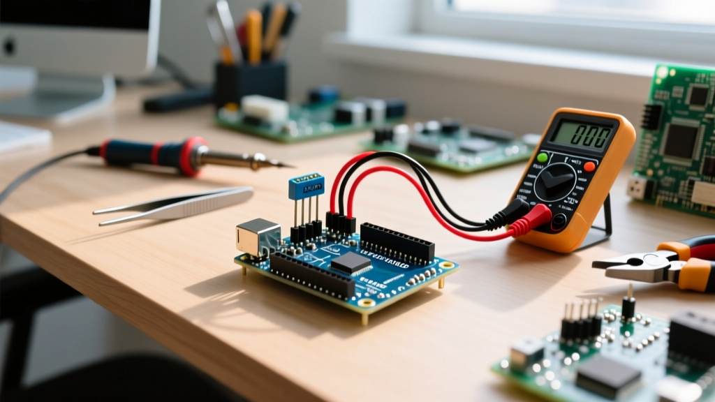

Common Reasons Ultrasonic Sensors Arduino Projects Fail
When building distance-measurement or obstacle-avoidance systems, the HC-SR04 remains the most widely deployed component in the maker ecosystem. However, integrating ultrasonic sensors Arduino circuits often leads to frustrating edge cases: ghost readings, hard lockups, and complete signal dropout. While the basic theory of 40kHz acoustic time-of-flight is simple, real-world physics and microcontroller timing constraints introduce significant complexity.
This advanced troubleshooting guide bypasses basic wiring tutorials and dives directly into the hardware failure modes, logic-level mismatches, and timing bottlenecks that cause ultrasonic sensor failures in 2026. Whether you are using an Uno R4, an ESP32, or a Raspberry Pi Pico, these diagnostic frameworks will isolate your exact point of failure.
Diagnostic Matrix: Symptom to Root Cause
Use this matrix to quickly map your specific failure mode to the underlying hardware or software bottleneck.
| Symptom | Probable Root Cause | Diagnostic Step | Engineering Solution |
|---|---|---|---|
| Readings stuck at 0 cm | Echo pin timeout / 5V logic mismatch | Measure Echo pin with oscilloscope during read | Implement NewPing library; add logic level shifter |
| MCU freezes randomly | Blocking pulseIn() function |
Check serial output for halted timestamps | Set strict timeout parameter (e.g., 38000µs) |
| Wildly jumping values | Acoustic crosstalk or power rail sag | Monitor 5V rail with multimeter during trigger | Add 100nF decoupling capacitor; stagger sensor triggers |
| Consistent offset error | Temperature-induced speed of sound drift | Compare sensor output to physical caliper measurement | Integrate BME280 for real-time acoustic compensation |
| Fails under 20cm | Transmitter membrane 'ringing' blind zone | Test target at 5cm, 10cm, and 15cm intervals | Switch to ToF laser (VL53L1X) for close-proximity reads |
Deep Dive 1: The Timeout Trap and MCU Lockups
The most common reason beginners abandon ultrasonic sensors Arduino projects is the microcontroller freezing entirely. This is almost always caused by the native Arduino pulseIn() function. By default, pulseIn() waits for a pulse to start and then waits for it to end. If the sensor fails to return an echo (due to sound absorption or a missed trigger), the function will block the main thread for up to 1 full second per failed read.
Expert Warning: Never use
pulseIn(pin, HIGH)without a timeout parameter in a production or robotics environment. A single missed echo will halt your motor control loop for 1000 milliseconds, causing catastrophic physical crashes in RC cars or drones.
The Software Fix: NewPing and Hardware Timers
Instead of relying on blocking software loops, migrate to the Arduino pulseIn documentation recommended alternative: utilizing hardware timers. The NewPing library utilizes timer interrupts to measure the echo pulse width asynchronously. Furthermore, it enforces a strict maximum distance timeout. Since sound travels roughly 343 meters per second at 20°C, a maximum range of 4 meters requires an echo round-trip time of roughly 23.3 milliseconds. Setting your timeout to 38000 microseconds (38ms) guarantees the MCU will never hang, even if the sensor is completely disconnected.
Deep Dive 2: The 3.3V Logic Level Mismatch
As the ecosystem shifts toward 3.3V microcontrollers like the ESP32-S3 and Raspberry Pi Pico, voltage mismatches have become the leading cause of hardware degradation. The standard HC-SR04 is a 5V device. When it receives a valid trigger, the Echo pin outputs a 5V HIGH signal.
Feeding a 5V signal directly into a 3.3V GPIO pin on an ESP32 violates the absolute maximum ratings of the silicon. While the ESP32 might survive this initially due to internal clamping diodes, it will eventually cause permanent GPIO degradation, resulting in 'floating' reads or a fried pin.
Hardware Solutions for 3.3V Systems
- The Voltage Divider (Cost: $0.05): Place a 1kΩ resistor in series with the Echo pin, and a 2kΩ resistor to ground. This scales the 5V output down to a safe ~3.33V.
- The RCWL-1601 Module (Cost: $1.80): This is a pin-compatible clone of the HC-SR04 designed specifically for 3.3V logic. It features an onboard voltage regulator and outputs a 3.3V Echo signal natively. In 2026, this is the recommended default for all ESP32 and RP2040 builds.
Deep Dive 3: Power Rail Sag and Acoustic Noise
Ultrasonic transducers require a sudden, high-current burst to generate the 40kHz acoustic wave. If your Arduino is powered via a weak USB connection or a depleted LiPo battery, this sudden current draw causes a momentary voltage sag on the 5V rail. The HC-SR04's internal analog comparator relies on a stable reference voltage; if VCC drops below 4.5V during the burst, the comparator fails to register the returning echo, resulting in a '0 cm' read.
The Decoupling Capacitor Fix
Solder a 100nF (0.1µF) ceramic capacitor directly across the VCC and GND pins on the back of the sensor PCB. This provides a localized energy reservoir to sustain the transmitter burst without pulling down the main microcontroller power rail. According to SparkFun's ultrasonic sensor experiment guides, local decoupling is mandatory when running multiple sensors on the same breadboard power bus.
Environmental Variables: Temperature and Target Material
Ultrasonic sensors do not measure distance; they measure time. The Arduino code then divides this time by the speed of sound. However, the speed of sound is not a static constant. It fluctuates based on ambient temperature according to the formula: v = 331.4 + (0.6 × T) where T is temperature in Celsius.
- At 0°C, sound travels at 331.4 m/s.
- At 30°C, sound travels at 349.4 m/s.
If your code hardcodes the speed of sound for a 20°C room, deploying the sensor in a freezing outdoor environment (0°C) will introduce a 5.4% measurement error. Over a 4-meter distance, this equates to a 21 cm discrepancy. For precision applications, wire a DS18B20 or BME280 temperature sensor to your Arduino and dynamically update the speed of sound variable in your loop().
Target Material Absorption
Not all surfaces reflect 40kHz waves equally. Hard plastics, wood, and concrete provide excellent acoustic reflection. However, heavy fabrics, acoustic foam, and angled surfaces will scatter or absorb the ultrasonic burst. If your robot is failing to detect a couch or a curtain, the sensor is not broken; the physics of acoustic absorption are at play. In these scenarios, you must supplement your ultrasonic array with infrared ToF sensors (like the VL53L1X) or mmWave radar modules.
Component Comparison: Choosing the Right Sensor for 2026
If troubleshooting reveals that the HC-SR04 is fundamentally unsuited for your environment, consider these specialized alternatives:
| Model | Best Use Case | Blind Zone | Typical Price (2026) |
|---|---|---|---|
| HC-SR04 | Indoor robotics, basic education | ~2 cm | $1.20 |
| JSN-SR04T | Outdoor, automotive, wet environments | ~20 cm (due to membrane ringing) | $4.50 |
| RCWL-1601 | ESP32 / 3.3V logic microcontrollers | ~2 cm | $1.80 |
| A02YYUW | Industrial, UART output, high precision | ~10 cm | $12.00 |
Final Hardware Verification Checklist
Before rewriting your code, verify these physical layer conditions:
- Trigger Pulse Width: Ensure your code sends exactly a 10-microsecond HIGH pulse to the Trigger pin. Pulses shorter than 10µs will be ignored by the sensor's internal logic gate.
- Wiring Length: Unshielded jumper wires longer than 30cm act as antennas, picking up EMI from nearby DC motors. Keep signal wires short, or use shielded twisted-pair cable for remote sensor mounting.
- Transmitter Degradation: Inspect the silver mesh of the transmitter. If it is dented, corroded, or coated in paint/dust, the acoustic impedance changes, severely reducing the maximum range.
By systematically isolating the power delivery, logic levels, and timing constraints, you can transform the notoriously finicky HC-SR04 into a highly reliable peripheral for your next embedded systems project.