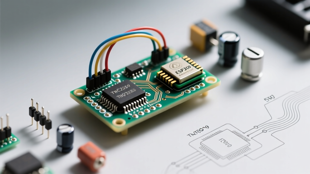

The Silicon Reality: Why the Datasheet Matters
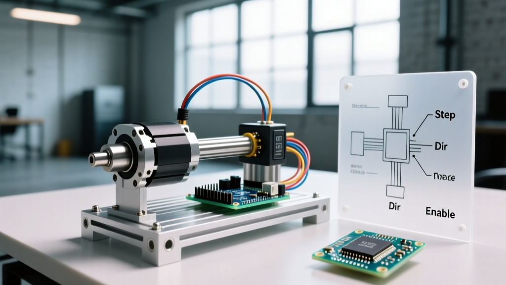
When integrating an arduino stepper driver into a custom CNC, 3D printer, or automated camera slider, hobbyists often rely on marketing copy rather than the silicon datasheet. In 2026, the Trinamic (now Analog Devices) TMC2209 remains the undisputed gold standard for silent, high-torque stepper motor control. However, the gap between a module's advertised '2A silent operation' and its real-world thermal performance is vast. This datasheet explainer decodes the TMC2209's hidden parameters, absolute maximum ratings, and UART configuration truths that separate reliable motion systems from skipped steps and melted MOSFETs.
Comparative Matrix: TMC2209 vs. Legacy Drivers
Before dissecting the TMC2209, it is critical to understand why legacy drivers fail in modern precision applications. Below is a technical comparison of the most common stepper driver ICs used with Arduino ecosystems.
| Parameter | TMC2209 (Modern Standard) | DRV8825 (Legacy Workhorse) | A4988 (Obsolete) |
|---|---|---|---|
| Max Continuous Current (w/ cooling) | 2.0A RMS | 2.2A RMS | 1.5A RMS |
| Microstepping Resolution | Up to 256x (via UART) | Up to 32x (Hardware pins) | Up to 16x (Hardware pins) |
| Control Interface | Step/Dir + Single-Wire UART | Step/Dir + Analog VREF | Step/Dir + Analog VREF |
| Sensorless Homing | Yes (StallGuard4) | No | No |
| Avg. Module Price (2026) | $8.00 - $14.00 | $2.50 - $4.00 | $1.50 - $2.50 |
While the Texas Instruments DRV8825 remains a budget-friendly option for simple conveyor belts, its audible resonance at low speeds and lack of dynamic current scaling make it unsuitable for acoustic-sensitive or high-precision environments.
Absolute Maximums & Thermal Throttling
Datasheet Warning: The TMC2209 datasheet specifies an absolute maximum motor supply voltage ($V_M$) of 29V. However, operating above 24V drastically increases the risk of voltage spikes during deceleration, which can punch through the internal MOSFETs and feed 24V directly into your Arduino's 5V logic rail, destroying the MCU instantly.
The Thermal Reality of 2A RMS
Marketing materials frequently advertise '2A continuous current.' The datasheet tells a different story. The TMC2209 features an internal thermal shutdown threshold at 150°C (junction temperature) and a warning flag at 120°C. In a standard 25°C ambient environment, a bare TMC2209 IC on a typical 2oz copper breakout board will hit thermal throttling at approximately 1.2A RMS without active airflow. To achieve the full 2.0A RMS, you must either attach a low-profile heatsink with forced convection or utilize the IC's dynamic current scaling features.
VREF vs. UART Current Configuration
In standalone (hardware) mode, you must set the current limit using the $V_{REF}$ potentiometer. The exact formula from the Analog Devices TMC2209 documentation is:
I_RMS = (V_REF * 0.325) / (R_sense * 2.5)
For a standard module with an $R_{sense}$ of 0.11Ω, targeting 1.0A RMS requires a $V_{REF}$ of exactly 0.84V. However, relying on the analog potentiometer is a relic of the past. By utilizing the single-wire UART interface, you can digitally set the IRUN and IHOLD registers, completely bypassing the physical potentiometer and enabling CoolStep dynamic current reduction.
Decoding Microstepping: StealthChop2 and SpreadCycle
The TMC2209 utilizes two distinct chopper algorithms, and understanding when to transition between them is crucial for avoiding missed steps at high RPMs.
- StealthChop2: A voltage-based PWM chopper that operates silently. It is ideal for low-to-medium speeds but suffers from torque drop-off and resonance at high velocities due to PWM frequency limitations.
- SpreadCycle: A current-based hysteresis chopper. It generates audible acoustic noise but maintains high torque and precision at high speeds.
The Datasheet Secret: You do not need to choose just one. Via UART, you can configure the TPWMTHRS register. This sets a velocity threshold. The driver will automatically use silent StealthChop2 during slow camera pans or 3D printer outer perimeters, and seamlessly switch to high-torque SpreadCycle during rapid travel moves.
StallGuard4: The Truth About Sensorless Homing
StallGuard4 allows the Arduino to detect when a motor hits a physical limit switch without actually wiring a switch. It measures the back-EMF and load angle on the motor coils. However, the datasheet explicitly notes several edge cases that trip up beginners:
- Minimum Velocity Requirement: StallGuard4 is physically incapable of detecting stalls at very low speeds. Your homing routine must accelerate the motor to at least 20-30 full steps per second before the DIAG pin will reliably trigger.
- The DIAG Pin is Active High: Unlike optical endstops that typically pull low, the TMC2209 DIAG pin pushes high (up to $V_M$ voltage). Never wire the DIAG pin directly to an Arduino input. You must use a voltage divider or a logic-level MOSFET to step the 12V/24V signal down to 5V/3.3V, otherwise you will fry the Arduino GPIO.
- SGTHRS Calibration: The stall threshold register (
SGTHRS) ranges from 0 to 255. A value too high will trigger false stalls during normal acceleration; a value too low will allow the motor to grind against the frame. Calibration must be done empirically via UART while monitoring theSG_RESULTregister.
Wiring the UART Interface to an Arduino
To unlock the TMC2209's full potential, you must wire the UART pin. The IC uses a single-wire serial protocol (TMC_UART), which requires a specific resistor network to separate TX and RX signals on a single Arduino pin.
Step-by-Step UART Wiring
- Connect the TMC2209
TXpin to the ArduinoRXpin via a 1kΩ resistor. - Connect the TMC2209
RXpin directly to the ArduinoTXpin. - Connect a 1kΩ resistor between the TMC2209
RXpin and GND (this acts as a pull-down to stabilize the line). - Ensure the module's MS1 and MS2 pins are configured correctly to set the UART slave address (0 to 3) if you are daisy-chaining multiple drivers on the same serial bus.
For comprehensive firmware integration, the Marlin Firmware TMC documentation provides exact macro definitions for mapping these UART addresses to specific axes.
Datasheet-Backed Troubleshooting Matrix
When your Arduino stepper driver setup fails, consult this matrix derived directly from TMC2209 errata and application notes.
| Symptom | Datasheet Root Cause | Actionable Fix |
|---|---|---|
| Motor vibrates but does not rotate at startup | Missing steps due to high static friction and low initial current. | Increase IHOLD register or implement a software 'kickstart' routine (high speed for 50ms before dropping to target speed). |
| Driver resets randomly during fast deceleration | Regenerative voltage spike exceeding 29V $V_M$ limit. | Add a 470µF low-ESR capacitor directly across the $V_M$ and GND terminals on the breakout board to absorb back-EMF. |
| Audible high-pitch whine in StealthChop mode | PWM frequency entering the human hearing range (approx. 18kHz). | Adjust the PWM_GRAD and PWM_OFS registers via UART to shift the base PWM frequency above 20kHz. |
| StallGuard triggers immediately upon homing | SGTHRS value set too high, or motor accelerating too fast. | Lower SGTHRS by 15% and implement an S-curve acceleration profile in your Arduino sketch. |
Final Thoughts on Peripheral Integration
Treating the TMC2209 as a simple 'drop-in' replacement for older drivers leaves 80% of its silicon capabilities untapped. By reading the datasheet, implementing the single-wire UART, and respecting the thermal and regenerative voltage limits, you transform a standard Arduino stepper motor project into an industrial-grade, whisper-quiet motion system. Always prioritize proper decoupling capacitors and logic-level shifting to ensure your microcontroller survives the harsh electrical environment of high-current motor driving.