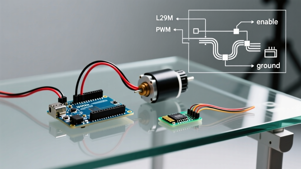

Introduction to Arduino Motor Control L298N
Despite the proliferation of modern MOSFET-based drivers, the Arduino motor control L298N setup remains a cornerstone of robotics and heavy-duty DIY electronics in 2026. The L298N dual full-bridge driver IC, originally designed by STMicroelectronics, is uniquely capable of handling high-voltage (up to 35V) and high-current (2A continuous per channel) brushed DC motors and stepper motors. However, simply wiring the module is only half the battle. To achieve smooth acceleration, dynamic braking, and reliable state management, you need a robust software driver.
This guide bypasses the bloated, legacy libraries of the past decade. Instead, we will explore the hardware realities of the L298N, build a highly optimized, bare-metal C++ driver class for modern Arduino architectures (AVR, ESP32, and RP2040), and address the critical thermal and PWM edge cases that cause 90% of field failures.
The L298N Architecture: Bipolar Realities in a MOSFET World
To write an effective driver library, you must understand the silicon you are commanding. Unlike modern drivers that use highly efficient N-channel and P-channel MOSFETs, the L298N relies on bipolar junction transistors (BJTs) configured in Darlington pairs. This architectural choice defines both its ruggedness and its primary weakness.
The Voltage Drop Penalty
According to the STMicroelectronics L298N Datasheet, the saturation voltage ($V_{CE(sat)}$) across the internal transistors typically ranges from 1.8V to 3.2V depending on the current draw. If you are powering a 12V motor and drawing 1.5A, the driver will dissipate roughly 2.7V to 4.8V as pure heat. This means your motor only receives ~8.5V, and the module must shed over 5 Watts of thermal energy. Your software driver must account for this by mapping PWM duty cycles to the effective voltage reaching the motor terminals, not the battery voltage.
Expert Warning: Never run the L298N at its absolute maximum rating of 2A continuous without an active cooling fan or a massive aftermarket heatsink. In standard 2026 hobbyist modules (like those from HiLetgo or Elegoo), the included aluminum fin is only sufficient for ~1.2A continuous draw at 25°C ambient.
Wiring and Power Routing for Software Reliability
Software glitches often stem from hardware brownouts. The L298N module features an onboard 5V linear regulator (typically an LM7805). How you configure the physical jumper dictates how your Arduino should initialize its pins.
- Motor Supply (VCC) < 12V: Leave the 5V EN jumper in place. The module powers the Arduino via the 5V pin. Your software can assume a stable 5V logic reference.
- Motor Supply (VCC) > 12V: Remove the 5V EN jumper immediately. The LM7805 will overheat and fail if the input exceeds 12V-14V. Power the Arduino separately via USB or its own regulator, and connect the Arduino GND to the module GND to establish a common logic ground.
Choosing the Right Arduino Motor Control L298N Library
Historically, hobbyists relied on the AFMotor library. However, this library was written for the Adafruit Motor Shield V1 and hardcodes AVR Timer1 and Timer2 configurations. If you are using an ESP32, a Raspberry Pi Pico (RP2040), or even an Arduino Uno R4 Minima in 2026, legacy libraries will cause compilation errors or PWM conflicts.
| Approach | Pros | Cons | Best For |
|---|---|---|---|
| Legacy Libraries (AFMotor) | Easy API, built-in stepper support | AVR-only, heavy SRAM usage, timer conflicts | Legacy Arduino Uno R3 projects |
| AccelStepper (for Steppers) | Excellent acceleration profiles | Overkill for simple DC motors, blocking code | CNC and precision stepper arrays |
| Custom Bare-Metal C++ Class | Zero dependencies, cross-platform, minimal overhead | Requires manual PWM setup, no built-in physics | Modern MCUs (ESP32, RP2040, AVR) |
Building a Modern, Cross-Platform C++ Driver Class
Instead of relying on outdated dependencies, we will write a lightweight, object-oriented C++ wrapper. This class handles pin initialization, direction logic, and PWM speed mapping while remaining agnostic to the underlying microcontroller architecture (provided it supports standard analogWrite() or LEDC/PWM equivalents).
#ifndef L298N_DRIVER_H
#define L298N_DRIVER_H

#include <Arduino.h>

class L298N_Driver {
private:
    uint8_t _in1, _in2, _ena;
    bool _isMoving;
    uint8_t _currentSpeed;

    // Internal helper to set logic pins safely
    void setLogic(bool forward) {
        digitalWrite(_in1, forward ? HIGH : LOW);
        digitalWrite(_in2, forward ? LOW : HIGH);
    }

public:
    L298N_Driver(uint8_t in1, uint8_t in2, uint8_t ena)
        : _in1(in1), _in2(in2), _ena(ena), _isMoving(false), _currentSpeed(0) {}

    void begin() {
        pinMode(_in1, OUTPUT);
        pinMode(_in2, OUTPUT);
        pinMode(_ena, OUTPUT);
        stop(); // Ensure safe state on boot
    }

    // Speed: 0 to 255. Accounts for L298N deadzone
    void setSpeed(uint8_t speed, bool forward = true) {
        if (speed > 0 && speed < 40) speed = 40; // Overcome static friction/BEMF
        _currentSpeed = speed;
        setLogic(forward);
        analogWrite(_ena, speed);
        _isMoving = (speed > 0);
    }

    // Dynamic Braking: Shorts motor terminals to halt quickly
    void brake() {
        digitalWrite(_in1, HIGH);
        digitalWrite(_in2, HIGH);
        analogWrite(_ena, 255);
        _isMoving = false;
        _currentSpeed = 0;
    }

    // Coast: Removes power, allows motor to spin down naturally
    void stop() {
        digitalWrite(_in1, LOW);
        digitalWrite(_in2, LOW);
        analogWrite(_ena, 0);
        _isMoving = false;
        _currentSpeed = 0;
    }
};
#endif
Understanding the Deadzone Compensation
Notice the line if (speed > 0 && speed < 40) speed = 40; in the code above. Because of the 2V+ voltage drop across the Darlington pairs, a PWM duty cycle below 15% (roughly 40 out of 255 on a 5V logic scale) often fails to overcome the motor's static friction and Back-EMF. This software-level compensation prevents the motor from emitting a high-pitched whine without actually turning.
Advanced PWM Frequency and Flyback Diode Limitations
When configuring Arduino motor control L298N systems, the default PWM frequency of the Arduino Uno (approx. 490 Hz or 980 Hz) is generally acceptable. However, if you are tuning for audio silence or specific torque curves, you might alter the timer registers to push PWM into the 20kHz+ range.
Critical Edge Case: The standard red L298N modules include 1N4007 flyback diodes. While excellent for low-frequency switching and protecting against massive inductive spikes, the 1N4007 has a slow reverse recovery time ($t_{rr}$). If you push your PWM frequency above 5kHz, these diodes cannot switch fast enough, leading to severe ringing, EMI generation, and eventual thermal runaway in the driver IC. If your software requires high-frequency PWM, you must physically desolder the 1N4007s and replace them with Schottky diodes (like the 1N5819) or fast-recovery UF4007 diodes.
L298N vs. Modern Alternatives: When to Switch Drivers
While mastering the L298N is a rite of passage, modern 2026 robotics often demand higher efficiency. Below is a decision matrix to help you choose the right hardware for your software stack.
| Feature | L298N Module | TB6612FNG Breakout | DRV8871 Carrier |
|---|---|---|---|
| Architecture | Bipolar (Darlington) | MOSFET | MOSFET |
| Max Continuous Current | 2A per channel | 1.2A per channel | 3.6A per channel |
| Voltage Drop | ~2.0V - 3.2V | ~0.5V | ~0.4V |
| Typical 2026 Cost | $3.50 - $6.00 | $4.50 - $8.00 | $6.00 - $9.50 |
| Best Software Use Case | High-voltage (24V) heavy rovers | Efficient 6V-12V micro-rovers | Single high-torque actuators |
Frequently Asked Questions (FAQ)
Why does my Arduino reset when the L298N motor starts?
This is a classic ground loop and voltage sag issue. Brushed DC motors draw a massive inrush current (stall current) upon startup. If your Arduino and the L298N logic share the same weak power supply, the voltage dips below the ATmega328P's brownout detection threshold (usually 2.7V or 4.3V). Solution: Use separate power supplies for the motors and the logic, ensuring their GND pins are tied together. Add a large electrolytic capacitor (e.g., 1000µF, 25V) across the motor power terminals on the L298N to buffer the inrush current.
Can I use the L298N to control a 24V linear actuator?
Yes, the L298N is rated for up to 35V. However, linear actuators draw significant current under load. Ensure your actuator's stall current does not exceed 2A. If it does, the L298N's internal thermal shutdown will trigger, or the IC will fail catastrophically. For actuators drawing 3A+, use a heavy-duty relay module or a high-current MOSFET driver like the BTS7960.
Does the L298N support regenerative braking?
No. The L298N lacks the internal circuitry to route Back-EMF back into the battery. When you invoke the brake() function in our custom library, it performs dynamic braking—shorting the motor terminals to convert kinetic energy into heat within the motor windings, bringing it to a rapid halt without recharging the battery.
Final Thoughts on Peripheral Interfacing
Mastering Arduino motor control L298N integration requires looking past simple copy-paste wiring diagrams. By understanding the thermal penalties of Darlington pairs, compensating for PWM deadzones in your C++ driver, and respecting the physical limits of onboard flyback diodes, you can build robust, heavy-duty robotic platforms that survive real-world deployment. For further reading on microcontroller PWM configurations and motor physics, consult the official Arduino Motor Documentation.


